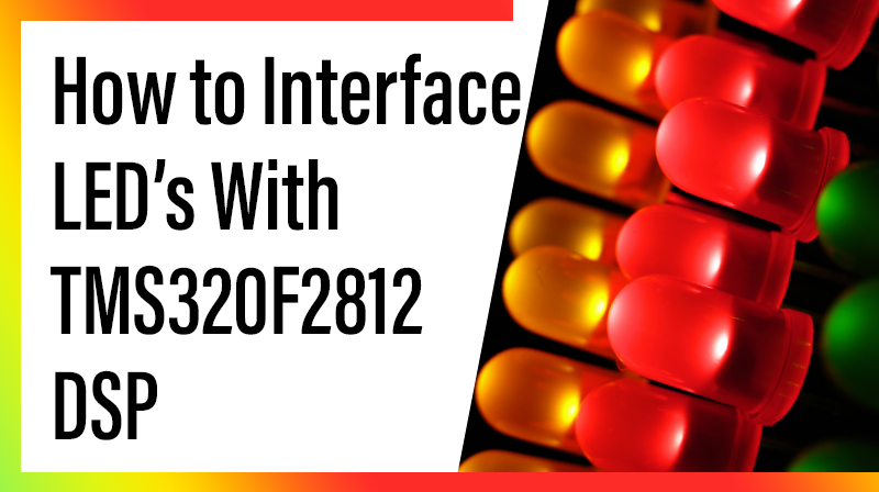
How to Interface LED’s With TMS320F2812 DSP
The TMS320F2812 EVALUATION BOARD is specially desgined for developers in dsp field as well as beginners. The F2812 kit is designed in such way that all the possible features of the DSP will be easily used by the everyone.The kit supports in Code Composer Studio3.1 and later, with XDS100 v1 USB Emulator which is done USB port.
LED
A Light Emitting Diodes (LEDs) are the most commonly used components, usually for displaying pin’s digital states.
Interfacing LED with TMS320F2812
The TMS320F2812 EVB board has Eight LED Connected with Dsp general purpose I/O pins. The Anode of each LED connects to ground and Cathode of each LED connects port via 220Ω resistor. To light an individual LED, drive the associated port signal to High.
Circuit Diagram to Interface LED’s with TMS320F2812 DSP
In TMS320F2812 KIT., F2812 processor port b is connected to the led(portb0, portb1,………portb7).
C program to Interface LED’s With TMS320F2812 DSP
Title: C Program to On/OFF LED using TMS320F2812 KIT
#include "DSP281x_Device.h"
#include
void Delay_1ms(long);
void main(void)
{
      EALLOW;
      SysCtrlRegs.WDCR= 0x0068;    // Setup the watchdog
// 0x0068 to disable the Watchdog , Prescaler = 1                           // 0x00AF to NOT disable the Watchdog, Prescaler = 64
      SysCtrlRegs.SCSR = 0;                  // Watchdog generates a RESET
      SysCtrlRegs.PLLCR.bit.DIV = 10;                // Setup the Clock PLL to multiply by 5
      SysCtrlRegs.HISPCP.all = 0x1;            // Setup Highspeed Clock Prescaler to divide by 2
      SysCtrlRegs.LOSPCP.all = 0x2;           // Setup Lowspeed CLock Prescaler to divide by 4
      GpioMuxRegs.GPAMUX.all = 0x0;   // all GPIO port Pin's to I/O
      GpioMuxRegs.GPBMUX.all = 0x0;
      GpioMuxRegs.GPADIR.all = 0x0;      // GPIO PORT as input
      GpioMuxRegs.GPBDIR.all = 0x00FF;        // GPIO Port B15-B8 input , B7-B0 output
      EDIS;
      while(1)
      {
        GpioDataRegs.GPBDAT.all = 0xFF;
        Delay_1ms(1000);                               //value 1000 for one second delay
        GpioDataRegs.GPBDAT.all = 0x0;
        Delay_1ms(1000);                                       //value 1000 for one second delay
       }
}

void Delay_1ms(long end)
{
        long i;
        for (i = 0; i <(9000 * end); i++);
}