Buzzer Interface with FPGA
Buzzer
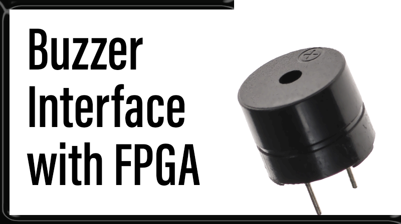
Piezo buzzer is an electric component that comes in different shapes and sizes, which can be used to create sound waves when provided with electrical signal. piezo buzzer requires a square wave to produce a tone.
Interfacing Piezo buzzer with FPGA
The FPGA Development Kit has Piezo buzzer, indicated as in Figure. Buzzer is driven by transistor Q1. FPGA can create sound by generating a PWM(Pulse Width Modulated) signal – a square wave signal, which is nothing more than a sequence of logic zeros and ones. Frequency of the square signal determines the pitch of the generated sound. To enable buzzer, place jumper JP at E label mark position and to disable buzzer place jumper JP at D Position.
Schematics to Interface Buzzer with FPGA
Buzzer Placement in Spartan3 FPGA Development Kit
VHDL Code Description:
The following VHDL Code demonstrates the functionality of piezo buzzer. PWM pulse is applied with 2s duty cycle. Buzzer produce beeps sound every 1 sec.
VHDL Code for Buzzer Interface with FPGA
library IEEE;
use IEEE.STD_LOGIC_1164.ALL;
use IEEE.STD_LOGIC_ARITH.ALL;
use IEEE.STD_LOGIC_UNSIGNED.ALL;

entity buzz is
port ( clock : in std_logic;
       a     : out std_logic
		 );
end buzz;

architecture Behavioral of buzz is

begin
process(clock)
variable i : integer := 0;
begin
if clock'event and clock = '1' then
if i <= 50000000 then
i := i + 1;
a <= '1';

elsif i > 50000000 and i < 100000000 then
i := i + 1;
a <= '0';

elsif i = 100000000 then
i := 0;
end if;
end if;
end process;
end Behavioral;
User Constraint File
NET "clock"  LOC = "p181"  ;
NET "a"  LOC = "p123"  ;