

Screaming Siren Circuit
Call for Price
Screaming Siren Circuit
Description
Screaming Siren Circuit
Introduction
siren is a device which is used to produce a loud noise. Different circuits produces a different noises.These sirenses can be used in emergency vehicles such as police cars, ambulances, fire engines etc.Screaming siren circuits are works depends upon the lights which fall on the siren, this circuits used in Light activated alarms.
Princilple
The main principle of this circuit is to produce sound depending on the light intensity falling on the circuit. As the light intensity falling on the circuit increases, it produces pulses with more duration and thus producing more sound. The main part of the circuit is 555 timer IC. This produces oscillations depending on the light intensity on the Light Dependent Resistor.
Circuit and Working
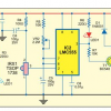
The main part of this light activated alarm circuit is 555 timer IC. It is mainly used in timing applications. It produces the oscillations required. This can be operated in three modes. These three modes are Monostable mode, Astable mode, Bistable mode. In this circuit, it is operated in astable mode. In this mode no external triggering is required. The second pin of the IC is connected to the sixth pin. Fourth pin is connected with the eight pin and is applied with a supply voltage of 5V. Third pin is connected to the speaker through a capacitor C1.
In astable mode, the second pin connected to the sixth pin continuously triggers the circuit. As the supply voltage of 5v is connected to the VCC the capacitor C2 starts charging through both the resistors LDR and R1.When the capacitor reaches 2/3 of VCC , the output pin 3 triggers and starts capacitor starts discharging through R1.Thus produces pulses at the output. When capacitor is at 1/3rd of VCC, it starts charging again.
The circuit mainly depends on the light dependent resistor for varying the sound in the circuit. These are also called photo resistors. Generally, light dependent resistors will have high resistance in darkness and it is decreased when they are illuminated with the light. The photo resistors used here are two mega ohm resistors i.e. they have resistance in the range of mega ohms in darkness. In the present circuit, two resistors LDR and the 1K ohm resistor are connected in series. These are connected to the capacitor C2 of 100nf. The two pins of sixth and second are shorted and connected to the same capacitor C2. Other end of the capacitor is connected to the ground.Speaker is another component that plays a vital role in the circuit. It takes the electrical signals and translates it into physical signal. This acts as a transducer. Inside the speaker there will a permanent magnet and the moving magnet. The electrical signals coming from the 555 timer IC are converted into the vibrations using these magnets. These vibrations are heard at output. Here the speaker used is 8ohms speaker. This should be connected to the output pin 3of the 555 timer IC through a electrolytic capacitor C1.Positive terminal of the capacitor is connected to the Pin 3 of the timer and negative terminal is connected to the positive terminal of speaker. Negative terminal is grounded.
Applications
- civil defense sirens to give warning at the time of natural disasters.
- This can be used in emergency signals.
Additional information
| Weight | 1.000000 kg |
|---|
Related products
-
- Out of StockRead more

- Mini Projects, NodeMcu Mini Projects
Water Quality Monitor
- Call for Price
-
-
- Out of StockRead more
- Mini Projects, NodeMcu Mini Projects
Air quality monitor
- Call for Price
-
-
- Out of StockRead more
-

Reviews
There are no reviews yet.