How to Interface LM35 Sensor with LPC2148 ARM7 Starter board
The ARM7 LPC2148 Starter Board is specifically designed to help students to master the required skills in the area of embedded systems. The kit is designed in such way that all the possible features of the microcontroller will be easily used by the students. The kit supports in system programming (ISP) which is done through serial port.
NXP’s ARM7 (LPC2148 ), ARM Starter Kit is proposed to smooth the progress of developing and debugging of various designs encompassing of High speed 32-bit Microcontrollers.
Temperature Sensor
The LM35 series are precision integrated-circuit temperature sensors, whose output voltage is linearly proportional to the Celsius (Centigrade) temperature. The output of sensor converted to digital that easy connecting with microcontroller.
Interfacing LM35
Fig. 1 shows how to interface the LM35 to microcontroller. As you can see the third pin is connected to GND, the first pin is connected to VCC & the second pin is connected to the Microcontroller input. Just use single PIN female to female wire to connect with the leads of LM35 temperature sensor. So when the temperature is sensing, it give the sensor reading to controller.

Interfacing LM35 with LPC2148
Read the temperature in LPC2148 Starter Board from temperature sensor LM35. The ARM7 LPC2148 Starter Board uses the ADC pin for reading temperature from temperature sensor LM35. The reading output is displayed into PC through UART1.
The 10 bit ADC used for reading the temperature from LM35. Basic clocking for the A/D converters is provided by the VPB clock. A programmable divider is included in each converter, to scale this clock to the 4.5 MHz (max) clock needed by the successive approximation process. A fully accurate conversion requires 11 of these clocks.
Pin Assignment with LPC2148
| Temp Sensor | LPC2148 Lines | Temperature Sensor | |
| LM35 | TempOutput | P0.28 | 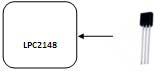 |
Circuit Diagram to Interface LM35 with LPC2148

Source Code
The Interfacing LM35 with LPC2148 program is very simple and straight forward, that reading temperature from temperature sensor LM35 and it display into PC through serial port. The C programs are written in Keil software. Some delay is occurring when a single data is sent to PC.
C Program to read temperature using LPC2148
***************************************************************************************
Title : Program to read temperature
***************************************************************************************
#include
#include
int volatile EINT1 	=	0;
int volatile EINT2	=	0;
void ExtInt_Serve1(void)__irq;
void ExtInt_Serve2(void)__irq;
/*----------------------------------<   INT2 Initialization  >------------------------------*/
void ExtInt_Init2(void)
{
	EXTMODE  |= 4;										//Edge sensitive mode on EINT2
	EXTPOLAR = 0;										//Falling Edge Sensitive
	PINSEL0  |= 0x80000000;								//Enable EINT2 on P0.15
	VICVectCntl1 = 0x20 | 16;							//Use VIC0 for EINT2 ; 16 is index of EINT2
	VICVectAddr1 = (unsigned long) ExtInt_Serve2;		//Set Interrupt Vec Addr in VIC0
	VICIntEnable |= 1<<16;								//Enable EINT2
}

/*----------------------------------<   INT1 Initialization  >------------------------------*/
void ExtInt_Init1(void)
{
	EXTMODE  |= 2;										//Edge sensitive mode on EINT1
	EXTPOLAR = 0;										//Falling Edge Sensitive
	PINSEL0  |= 0x20000000;								//Enable EINT1 on P0.15
	VICVectCntl0 = 0x20 | 15;							//Use VIC0 for EINT1 ; 15 is index of EINT2
	VICVectAddr0 = (unsigned long) ExtInt_Serve1;		//Set Interrupt Vec Addr in VIC0
	VICIntEnable |= 1<<15;								//Enable EINT1
}

/*----------------------------------<   Serial Initialization  >------------------------------*/
void Serial_Init(void)
{
	PINSEL0 |=	0X00000005;					//Enable Txd0 and Rxd0
	U0LCR 	=	0x00000083;	  				//8-bit data, no parity, 1-stop bit
	U0DLL	=	0x00000061;					//XTAL = 12MHz (pclk = 60 MHz, VPB = 15MHz(pclk=cclk/4)
	U0LCR	=	0x00000003;					//DLAB = 0;
}
/*------------------------------------<   Delay Function  >----------------------------------*/
 void DelayMs(unsigned int count) 	{


    unsigned int i,j;
    for(i=0;i<count;i++)
	{
		for(j=0;j<1000;j++);
	}
}

/*------------------------------------<   Main Function  >----------------------------------*/

void main(void)
{
	Serial_Init();
	ExtInt_Init1();							//Initialize Interrupt 1
	ExtInt_Init2();							//Initialize Interrupt 2

	putchar(0x0C);
	printf ("***************** External Interrupt Demo ***************************\n\n\r");
	DelayMs(100);
	printf (">>> Press Interrupt Keys SW2(INT1) and SW3(INT2) for Output... \n\n\n\r");
	DelayMs(100);

	while(1)
	{
		DelayMs(500);
		printf("INT1 Generated : %d  |  INT2 Generated : %d \r", EINT1, EINT2);
		DelayMs(500);
	}

}

/*----------------------------------<   Interrupt Sub-Routine  >------------------------------*/

void ExtInt_Serve1(void)__irq
{
	++EINT1;
	EXTINT |= 2;
	VICVectAddr = 1;
}

void ExtInt_Serve2(void)__irq
{
	++EINT2;
	EXTINT |= 4;
	VICVectAddr = 0;
}
To compile the above C code you need the KEIL software. They must be properly set up and a project with correct settings must be created in order to compile the code. To compile the above code, Temp Sens.c file must be added to the project.
In Keil, you want to develop or debug the project without any hardware setup. You must compile the code for generating HEX file. In debugging Mode, you want to check the port output without microcontroller Board.
The Flash Magic software is used to download the hex file into your LPC2148 Starter Board through UART0.
Testing the LM35 Based Thermometer with LPC2148
Give +3.3V power supply to LPC2148 Starter Board; the serial cable is connected between the controller and PC. Open the Hyper Terminal screen, select which port you are using and set the default settings. Now the screen should show the current temperature readings.
Bring a Hot soldering iron tip near the LM35’s pins, don’t touch it keep it 1 or 2mm away. The screen should update with the rising temperature. Now finally touch the pins of LM35 with the tip of iron, the temperature should rise quickly. Keep it there until temperature rise to 80 degrees, and then remove the iron.
General Information
- For proper working use the components of exact values as shown in Circuit file. Wherever possible use new components.
- Solder everything in a clean way. A major problem arises due to improper soldering, solder jumps, and loose joints.
- Use the exact value crystal shown in the schematic.
- More instructions are available in the following articles,
Interfacing UART with LPC2148 Microcontroller