
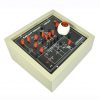

Single Phase Semi Converter
₹24,000.00 Exc Tax
Single Phase Semi Converter
Out of stock
Description
Features of Single Phase Semi Converter
- All Components are terminated with a connector for the study of Students.
- One Potentiometer is provided for varying the Firing angle a.
- TCA785 based Firing Scheme.
- Both half wave and full wave rectifier experiments can be done in single module.
- Inbuilt power supply for converter.
- Inbuilt Lamp Load.
- Inbuilt triggering circuit.
- Power ON indication Switch for power circuit and triggering module.
- All the junction points are terminated with a banana connector.
Experiments
- Single Phase Semi controlled converter with R load.
- Single Phase Semi controlled converter with RL load.
- Single Phase half wave Rectifier.
Technical Specification
- Kit Working voltage :(220-240)VAC
- Input Voltage : 110 V AC
- Output Current : 2A
- Input Frequency : 50Hz
- Firing Angle Variation : 0-180 degree
Bundle Contents
- SCR based Half Wave Controlled Converter.
- Patch cards.
- 6A power supply card.
- 2A Fuse.
- Manual.
- 100W Lamp.
Accessories
- RHEOSTAT R-LOAD
- Value 0-200 Ohm 2 A
- INDUCTOR L-LOAD
- Value 0-120mh Multitapping
Additional information
| Weight | 10.000000 kg |
|---|
Related products
-
- Out of StockRead more

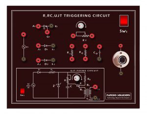
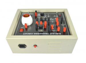
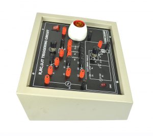
- Power Electronics
R,RC,UJT,Triggering
- Call for Price
-

-

-

-

-
-
-
- Out of StockRead more

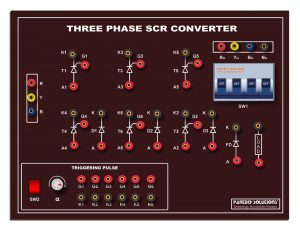
- Power Electronics
Three Phase AC Voltage Controllers
- Call for Price
-

-
-
- Out of StockRead more

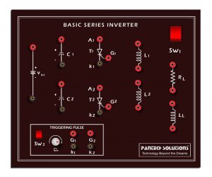
- Power Electronics
Series Inverter
- Call for Price
-
-
Reviews
There are no reviews yet.