128X64 GLCD Interface with FPGA
128×64 GLCD interfacing with Xilinx Spartan 6 FPGA project Board
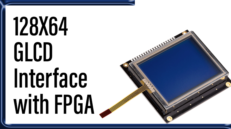
128×64 GLCD
A liquid crystal display (LCD) is a flat panel display that uses the light modulating properties of liquid crystals (LCs).
The 128×64 LCD is divided into two equal halves with each half being controlled by a separate KS0108 controller. Such LCDs (using KS0108 controller) involve paging scheme, i.e., whole LCD is divided equally into pages. The paging scheme of the graphical LCD can be easily understood from the following table.
The KS0107B is an LCD driver LSI with 64 channel outputs for dot matrix liquid crystal graphic display systems. This device provides 64 shift registers and 64 output drivers. It generates the timing signal to control the KS0108B (64 channel segment drover.). The KS0107B is fabricated by low power CMOS high voltage process technology, and is composed of the liquid crystal display system in combination with the KS0108B.
GLCD Pin Details
Interfacing 128×64 GLCD with Xilinx Spartan 6 FPGA project Board
The Xilinx Spartan 6 FPGA project Board has 128×64 GLCD, indicated as in Figure. 14 pins are needed to create 8-bit interface; 8 data bits (DB0-DB7), two chip select line (CS1) and (CS2), address bit (R/S), read/write bit (R/W) and control signal (E) and Reset (RST). The GLCD controller is a standard S6B0108 or equivalent, which is a very well-known interface for Graphical based LCDs. Figure below illustrate the GLCD part of the design and which pins are used for the interface. The GLCD is powered from the 5V power supply enabled by switch SW1.
Schematics to interface Xilinx Spartan 6 FPGA project Board
VHDL Code Description
The following 128×64 GLCD Code display Graphical Values for Pantech Solutions. When sending Data values enable input is active high. When sending Command value enable value is active low. RW is always maintained as active low. Reset is set to active high.
VHDL Code for 128×64 GLCD
library IEEE;
use IEEE.STD_LOGIC_1164.ALL;
use IEEE.STD_LOGIC_ARITH.ALL;
use IEEE.STD_LOGIC_UNSIGNED.ALL;


entity glcd is
port ( clk : in std_logic; --clock input
rst : out std_logic; --reseting of lcd
cs1 : out std_logic; --control signal for display1
cs2 : out std_logic; --control signal for display2
rw : out std_logic; --read&write enable
di : out std_logic; --data input control
lcd_e : out std_logic; --enable signal
data : out std_logic_vector(7 downto 0)); --data line
end glcd;

architecture Behavioral of glcd is

constant N: integer := 183;

type arr is array (1 to N) of std_logic_vector(7 downto 0);

constant datas : arr := (X"49",X"ba",X"c4",

X"00",X"ee",X"ee",X"ee",X"ee",X"ee",X"ee",x"f0",x"ff",x"ff",x"ff", --p
X"00",X"ee",X"ee",X"ee",X"ee",X"ee",X"ee",x"00",x"ff",x"ff",x"ff", --a
X"00",X"fd",X"fb",X"f7",X"ef",X"df",x"bf",x"00",x"ff",x"ff",x"ff", --n
X"fe",X"fe",X"fe",X"00",X"fe",X"fe",X"fe",X"fe",x"ff",x"ff",x"ff", --t
X"00",X"76",X"76",X"76",X"76",X"76",X"76",X"76",x"ff",x"ff",x"ff", --e

X"49",X"bc",X"c4", --59 60 61

X"f0",X"6e",X"6e",X"6e",X"6e",X"6e",X"6e",x"0f",x"ff",x"ff",x"ff", --s
X"00",X"7e",X"7e",X"7e",X"7e",X"7e",X"7e",x"00",x"ff",x"ff",x"ff", --o
X"00",X"7f",X"7f",X"7f",X"7f",X"7f",X"7f",X"7f",x"ff",x"ff",x"ff", --l
X"00",X"7f",X"7f",X"7f",X"7f",X"7f",X"7f",x"00",x"ff",x"ff",x"ff", --u
X"fe",X"fe",X"fe",X"00",X"fe",X"fe",X"fe",X"fe",x"ff",x"ff",x"ff", --t

X"40",X"ba",X"c4", --117 118 119

X"00",X"7e",X"7e",X"7e",X"7e",X"7e",X"7e",X"7e",x"ff",x"ff",x"ff", --c
X"00",X"f7",X"f7",X"f7",X"f7",X"f7",X"f7",x"00", --h

X"40",X"bc",X"c4", --140 141 142

X"7e",X"7e",X"7e",X"00",X"7e",X"7e",X"7e",X"7e",x"ff",x"ff",x"ff", --i
X"00",X"7e",X"7e",X"7e",X"7e",X"7e",X"7e",x"00",x"ff",x"ff",x"ff", --o
X"00",X"fd",X"fb",X"f7",X"ef",X"df",x"bf",x"00",x"ff",x"ff",x"ff", --n
X"f0",X"6e",X"6e",X"6e",X"6e",X"6e",X"6e",x"0f",X"3f"); --s

---command and data to be display

begin

process(clk)

variable i : integer := 0;
variable j : integer := 1;

begin

rw <= '0'; --lcd write
rst <= '1'; --reset off

if j <= 183 then
if clk'event and clk = '1' then
if i < 500 then --timing delay for lcd on/off
i := i + 1;
lcd_e <= '1';
data <= datas(j);
elsif i >= 500 and i < 1000 then
i := i + 1;
lcd_e <= '0';
elsif i = 1000 then
lcd_e <= '0';
j := j + 1;
i := 0;
end if;
end if;
end if;

if j <= 3 or j = 59 or j = 60 or j = 61 or j = 117 or j = 118 or j = 119
or j = 139 or j = 140 or j = 141 or j = 183 then
--control logic for data and command
di <= '0';
elsif j > 3 then
di <= '1';
end if;
if j <= 115 then --control logic for 2 displays on/off
cs1 <= '0';
cs2 <= '1';
elsif j > 115 and j <= 182 then
cs1 <= '1';
cs2 <= '0';
elsif j >= 183 then
cs1 <= '1';
cs2 <= '1';
end if;
end process;
end Behavioral;
User Constraint File
NET "clk" LOC = P85;
NET "cs1" LOC = P7;
NET "cs2" LOC = P6;
NET "data[0]" LOC = P22;
NET "data[1]" LOC = P21;
NET "data[2]" LOC = P17;
NET "data[3]" LOC = P16;
NET "data[4]" LOC = P15;
NET "data[5]" LOC = P14;
NET "data[6]" LOC = P12;
NET "data[7]" LOC = P11;
NET "di" LOC = P9;
NET "lcd_e" LOC = P10;
NET "rw" LOC = P8;