


Parallel Inverter
Call for Price
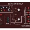
Parallel inverter circuit consists of two SCRs T1 and T2, an inductor L, an output transformer and a commutating capacitor C. The output voltage and current are Vo and Io respectively. The function of L is to make the source current constant. During the working of this inverter, capacitor C comes in parallel with the load via the transformer. So it is called a parallel inverter.
Description
Features of Parallel Inverter
- All Components are terminated with a connector for the study of Students.
- One potentiometer is provided to change the Inverter output frequency.
- Inbuilt 555 IC based PWM generation.
- Separate Inbuilt Power Supply for Triggering Pulse and Power Inverter Circuit.
- Inbuilt Resistive Load.
- 2 no’s of 1:1 Pulse transformers are used for isolated triggering of the SCR.
- Detailed mimic diagrams are drowned to facilitate the experiments.
- All the junction points are terminated with banana connector for monitor/measure and study of signals using any one of measuring equipments.
Experiments
- Design and construction of Parallel Inverter with R Load
- Design and construction of Parallel Inverter with RL Load
Technical Specification
- Kit Working voltage :(220-240)VAC
- Input Voltage :30 V DC
- Output Voltage :30 V AC
- Output Current :1 Amps
- Output Frequency :0- 50Hz
Bundle Contents
- Single Phase Parallel Inverter Module
- atch cards
- 6A power supply card
- 2A Fuse
- Manual
Accessories
-
RHEOSTAT R-LOAD
- Value 0-200 Ohm 2 A
-
INDUCTOR L-LOAD
- Value 0-120mh Multitapping
Additional information
| Weight | 1.000000 kg |
|---|
Related products
-
- Out of StockRead more
- Power Electronics
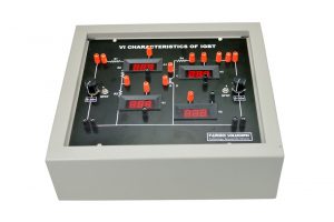
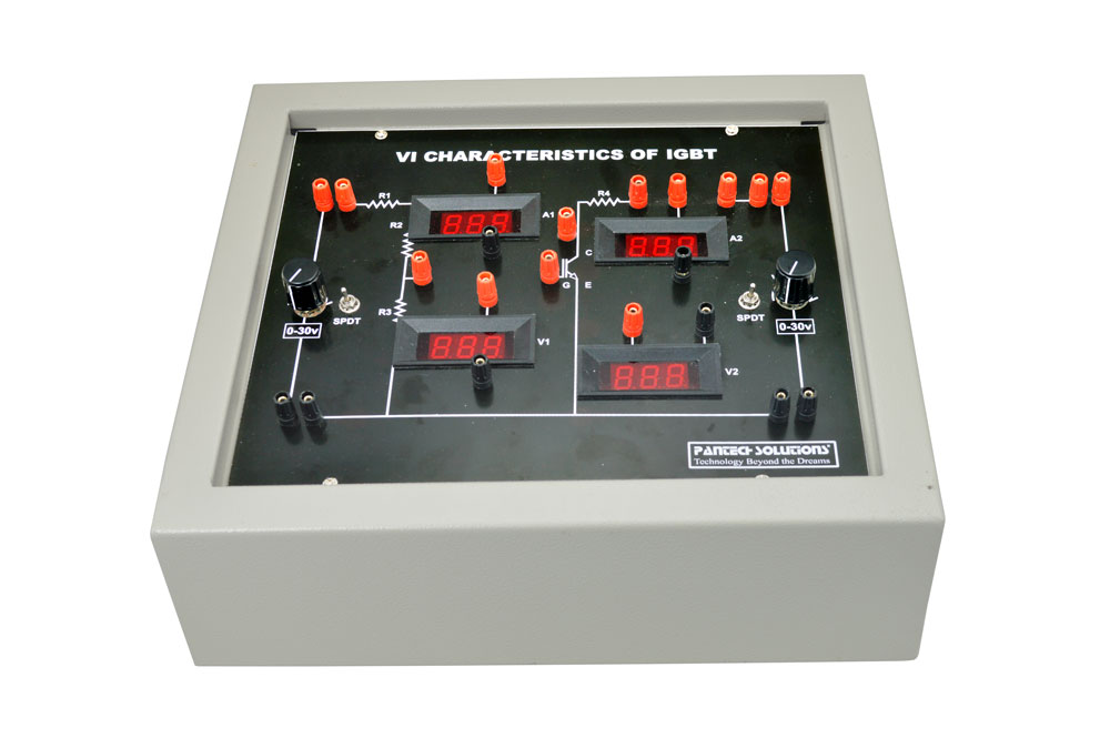
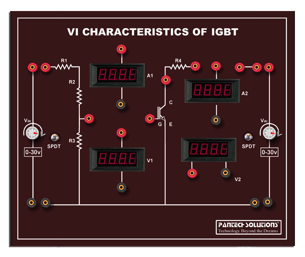
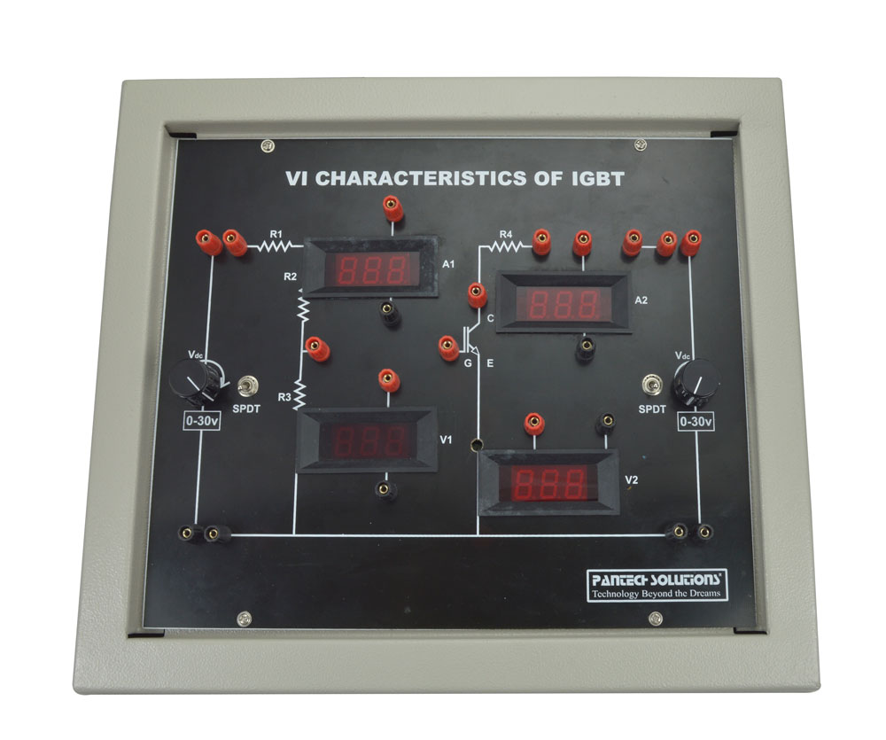
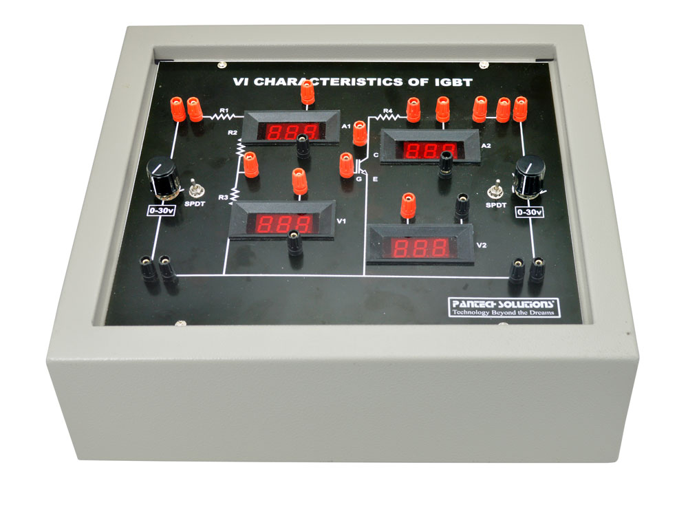
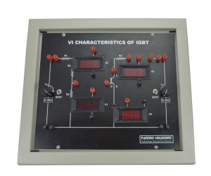
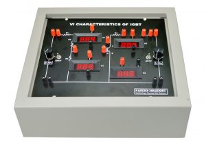
V-I Characteristics of IGBT
- Call for Price
-
-
-
-
-

-
-
- Out of StockRead more
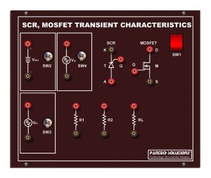
- Power Electronics
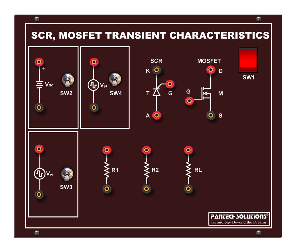
Transient Characteristics of SCR and MOSFET
- Call for Price
-
-
-
- Out of StockRead more
- Power Electronics
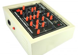
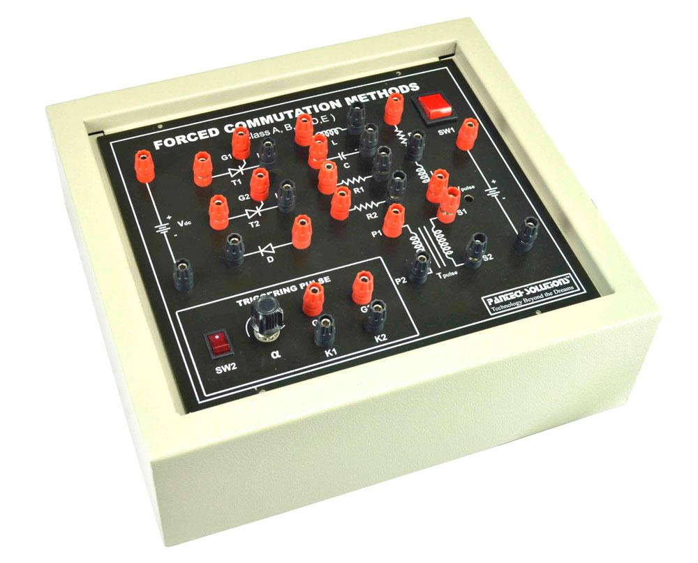
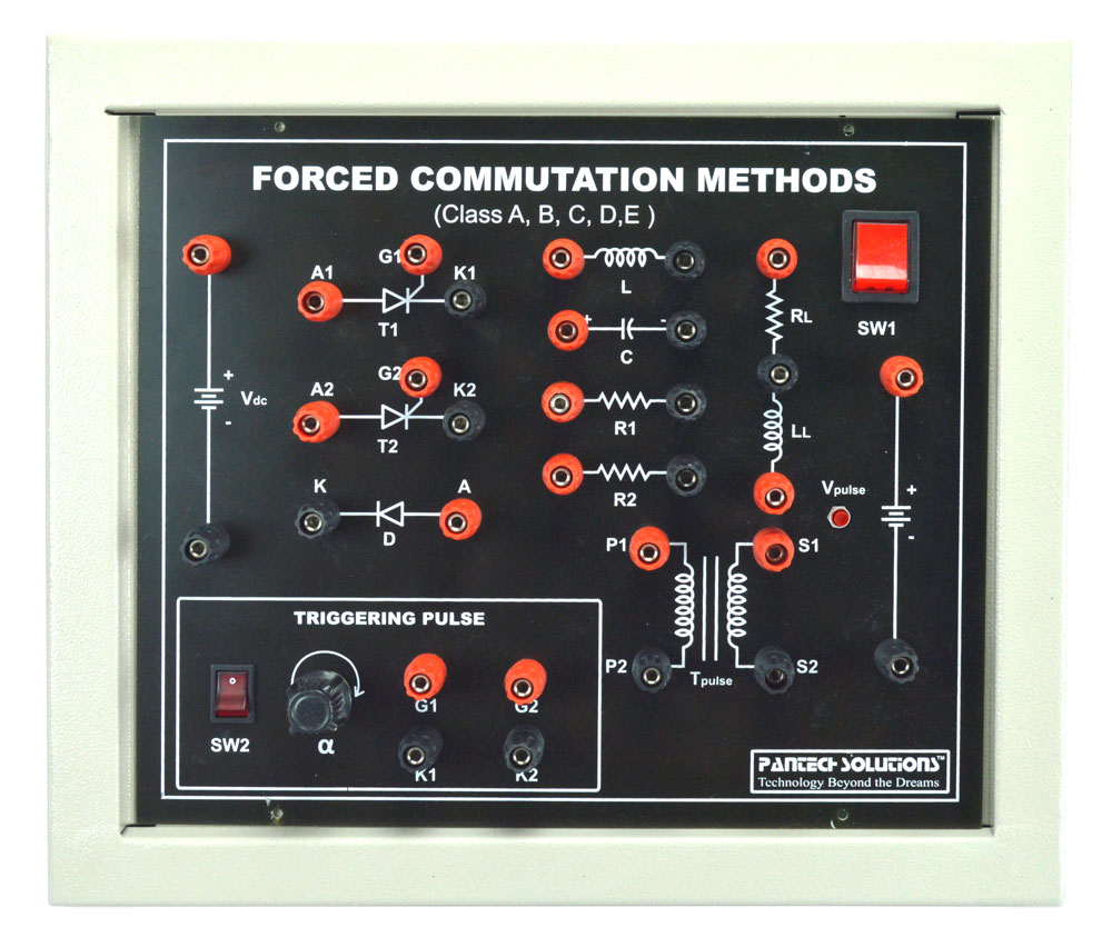
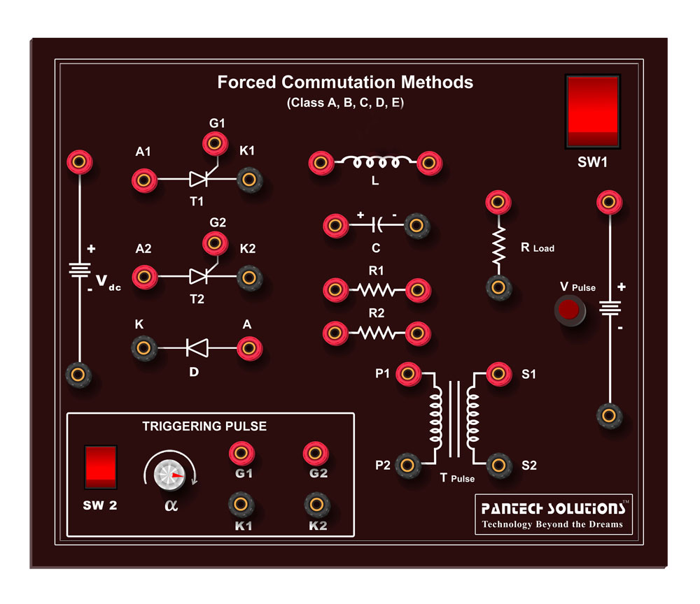
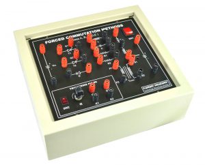
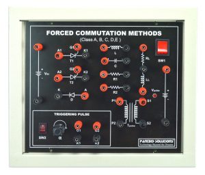
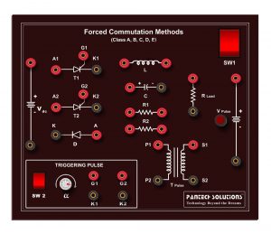
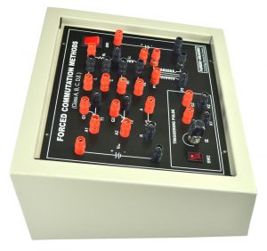
Forced Commutation Class A,B,C,D,E
- Call for Price
-

-
-
-
-

-

Reviews
There are no reviews yet.