Getting Started with USB PIC Programmer
Introduction
The PICKIT2 PROGRAMMER is a programmer board which demonstrates the capabilities of the 5V PIC16, PIC18 and dsPIC devices.
This Board can be used as stand-alone board built with an in-circuit USB programmer. Sample programs are provided to demonstrate the unique features of the supported devices.
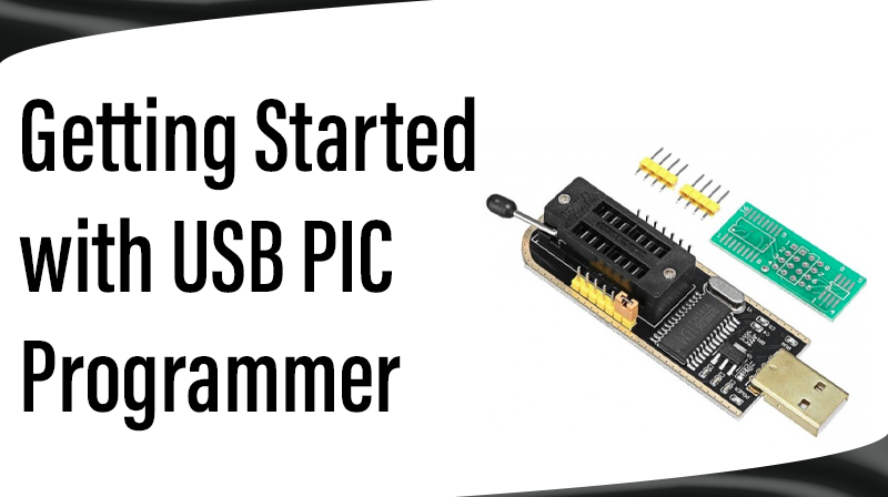
The PICKIT2 Clone comes with the following:
- PICKIT2 Clone board
- PICKIT2 Adapter Board
- USB Cable
- CD-ROM, which contains:
– Software’s
– User’s Guide
Note: If you are missing any part of the kit, please contact our support executive
PICKIT2 CLONE PROGRAMMER BOARD
The PICKIT2 programmer board has the following hardware features:
- Two 40-pin ZIF sockets for programming various IC’s (Add-on Board)
- USB +5V Supply (No external Supply)
- Supports all +5V Flash Controllers
- Busy LED indication and Power Supply Indication
- 14 Pin Box connector Termination
- Programmer Button select option
- Option to connect ICD2 with adapter board
- Option to use programmer and adapter separately
PICKIT2 HARDWARE
SAMPLE DEVICES
No Sample device (IC) is included.
PICKIT2 BOARD LAYOUT
HARDWARE DETAILS
Connector Details
J3, the ICSP connector has 14 pins, but the ICSP of PIC needs only five pins. So the pins are connected as following, the topside pins and the parallel pins from bottom side are referred by the same name.
| PIN | DESCRIPTION |
| MCLR | VPP pin. MCLR on top side and the parallel pin from bottom side supplies MCLR |
| VDD | +ve supply. VDD on top side and the parallel pin from bottom side supplies VDD |
| GND | GND supply. GND on top side and the parallel pin from bottom side supplies GND |
| PGD | Program Data |
| PGC | Program Clock |
| AUX, NC | No connection pins |
Connector J1
This connector is used to load firmware on 18F2550. The user of this board is not needed to modify or load the firmware. It is preloaded by factory.
Pin details from right to left (Button side).
| PIN NUMBER | DESCRIPTION |
| 1 | MCLR |
| 2 | VDD |
| 3 | VSS |
| 4 | PGD |
| 5 | PGC |
| 6 | NC |
Power Supply
PICKIT2 v2.1 takes power from USB; however the supply to the target board can be given externally by using add-on board
HARDWARE DETAILS ADD-ON
Pickit2 Adapter Board Layout
PICKIT2 adapter board is designed to support many IC’s. Two ZIF sockets provided to support various IC’s. ZIF J2 used to program 28 pin 16F/18F and 40 Pin dsPIC IC’s whereas ZIF J1 support 8/14/20/18 and 40 pin Flash based 10F/12F/16F/18F IC’s.
Connector and Switches
J3, the ICSP connector has 14 pins, but the ICSP of PIC needs only five pins. So the pins are connected as following, the topside pins and the parallel pins from bottom side are referred by the same name.
| PIN | DESCRIPTION |
| J1 | ZIF socket to program 10/14/18/20/40 pin IC’s |
| J2 | ZIF socket to program 40 pin dsPIC and other 28 pin IC’s |
| J3 | ICSP Connector used to make connection with PICKIT2 Clone |
| J4 | ICD2 Connector, used to connect this add-on board with ICD2 (optional) |
| SW1 | 40 pin dsPIC or 28 Pin (dsPIC or other) IC select switch |
| DC JACK | External 5V supply for IC’s (Beware of >5V supply because of no regulator |
Placement of IC’s for Programming
8/14/18 pin IC’s on ZIF Socket J1
The first pin of IC’s must be placed at the 10th pin of ZIF socket. For easy identification the pin is marked as 10 on the right side of the ZIF socket J1.
20 pin IC’s on ZIF Socket J1
The 10 th pi of ic must be placed at the 20-pin ZIP Socket i.e. place the ic as the bottom side of IC placed on the bottom side of ZIF Socket J1.
40 pin IC’s on ZIF Socket J1
Place the IC’s as regular.
28 pin IC’s on ZIF Socket J2
The first pin of IC’s must be placed at the first pin of ZIF socket i.e. place the ic as the top side of IC placed on the top side of ZIF Socket J2. Turn ON SW1 to 28 Pin side.
40 pin dsPIC’s on ZIF Socket J2
Place the IC’s as regular and Turn ON SW1 to 30F4013 side.
Configuring the PIC Programmer Board
1. First attach the PIC Microcontroller Programmer Board with PC via USB cable.
2. Wait until the Pickit2 Finishes Driver Installation. If the driver not detected just try to reconnect or Restart your system, then try again.
3. After Finishing the Hardware driver installation. Open up MPLAB IDE. Select Programmer-> Select Programmer → PICkit2
4. If the Kit is properly connected, you can see the Pickit2 Icon set on the Toolbar (Yellow Set) and the PICkit2 Ready Message. Very First icon is used for “Programming the device”.
5. Finally open our Example Programs, Burn into the controller, do the hardware connection as per Chapter 2 and See the result.
Possible Errors
Error 1: MPLAB may throw “Write Failure-Get lost Error”. If it does, follow the instructions below,
- Unplug the Power supply from target board
- Close MPLAB
- Plug the AC/DC adapter
- Reopen MPLAB
Error 2: MPLAB may throw “target not found” error, If it does, follow the instructions below,
- Ensure whether the PIC microcontroller placed properly in ZIF jacket.
- In Configure–>Select device, ensure PIC16f877A (or any) is selected.
Error 3: MPLAB may throw “Verified Failed” error, due to the following
- Hex File may be old, so compile the project once and try Programming.
- Faulty microcontroller device, Replace it with new one.
Note *: If the error still retains check your windows firewall or antivirus software to allow this MPLAB and Pickit2 programmer.
BURNING A PROGRAM
Programming an IC using MPLAB
1. Connect the PICKit2 Programmer with ADDON card using 14 pin FRC cable
2. Place the IC as per chapter 3.3
3. Connect a USB cable between PC and PICKit2 Clone Hardware Kit
4. Open MPLAB and Select Programmer → Select Programmer → PICkit2.
5. In output window(View → Output) you can see the following information,
6. Select File → Import in MPLAB
7. Select the Hex file (Navigate) to be programmed. Click Open
8. From the ICON set, Click Program the device (The First one)
9. Now you can see the Program successfully message in Output Widow
Programming an IC using Pickit2
1. Install the PICKit2 Programmer software comes with User CD.
2. Connect the PICKit2 Programmer with ADDON card using 14 pin FRC cable
3. Place the IC as per chapter 3.3
4. Connect a USB cable between PC and PICKit2 Clone Hardware Kit
5. Double Click to open PICKit2 programmer icon.
6. It will be automatically connected with the board and will show you like the following window.
7. Select File → Import Hex
8. Navigate to the directory where the Hex file is located. Select the Hex file and Click Open
9. Now the Hex file is Successfully Imported
10. Click the Write button.
11. Now the IC is successfully programmed. Remove the IC from socket. Place it in your target Hardware. Start running the code.