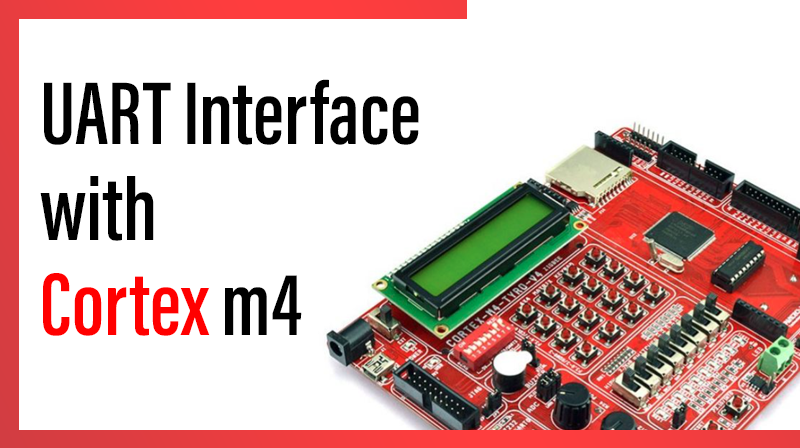
UART Interface with Cortex m4
This example describes how to make UART communication via UART0
Procedure for UART Interface with Cortex m4
- Power: In the PCONP register, set bit PCUART0
- Configure pins P0.2 and P0.3 as UART0 TX and RX using IOCON_P0_2 and IOCON_P0_3.
- Select Clock source and frequency
- Set no. of data bits, stop bit, parity and Give access to Baud rate register
- Derive baud rate from the UART clock source
- Check the Transmitter flag, If it is High Transmit a character
- Check the Receiver flag for data ready. If the data is ready Read the character
UART Interface with Cortex m4 -C source code
#include "LPC407x_8x_177x_8x.h"

unsigned char recval=0, welstring[]="Hi: Press a Key\r\n";

unsigned char UART0_Receive(void);
void UART0_Txmt(unsigned char Chr);
void init_serial(void);
void UART0_puts(unsigned char *string);

int main(void)
{
		init_serial();
		UART0_puts(welstring);
		while(1)
		{
			recval=UART0_Receive();
			UART0_Txmt(recval);
		}
}


void init_serial(void)
{
		//1. set bit PCUART0
		LPC_SC->PCONP |= (1 << 3); 										/* enable power to UART0*/

		//2. Configure pins P0.2 and P0.3 as UART0 TX and RX
		LPC_IOCON->P0_2 |=  1;        								/* Pin P0.2 used as TXD0 */
		LPC_IOCON->P0_3 |=  1;        								/* Pin P0.3 used as RXD0 */

		//3.Select Clock source and frequency=PCLK ie 30MHz
		/* 8 bits, no Parity, 1 Stop bit   */
		// Set DLAB=1 to access baud rate Register
		LPC_UART0->LCR    = 0x83;

		//4. Derive baud rate from the UART clock source,
		//DLM:DLL=PCLK/(16*baud)= 30Mhz/(16*9600)= 195
		LPC_UART0->DLL    = 195;                      /* 9600 Baud Rate @ 30.0 MHZ PCLK*/
		LPC_UART0->DLM    = 0;                        /* MSB = 0 */
		LPC_UART0->LCR    = 0x03;                     /* DLAB = 0*/
}

//Transmit a character
void UART0_Txmt(unsigned char Chr)
{
	//6. Check the Transmitter flag
	//   If it is High Transmit a character
		while((LPC_UART0->LSR & 0x20)==0);
		LPC_UART0->THR = Chr;
}

//Receive a character
unsigned char UART0_Receive(void)
{
		//7.Check the Receiver flag for data ready
		//  and Read the character
		while((LPC_UART0->LSR & 0x01)==0);
		return(LPC_UART0->RBR);
}

//Transmit a string
void UART0_puts(unsigned char *string)
{
		while(*string)
		UART0_Txmt(*string++);
}