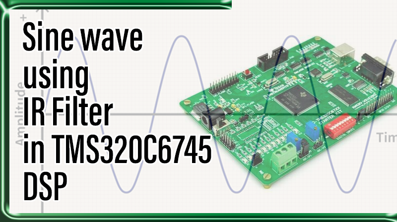
Sine wave using IR Filter in TMS320C6745 DSP
Aim
To Generate a sinewave using IIR Filter in TMS320C6745 DSP KIT.
Requirements
☞CCS v4
☞USB Cable
☞5V Adapter
Theory
There are several ways to implement the sine wave generator on DSP processor such as a lookup table, interpolation, polynomials, etc. One efficient technique is using an IIR filter, making it oscillating by locating its poles in the unit circle of the Argand diagram. A typical 2nd order IIR filter can be established as illustrated in Figure 1. Give this IIR two initial values as below based on the assumption of 40 samples to make up a complete sine wave, then disconnect the
Figure 1. 2nd Order filter for genarating since wave
x[n] from the input. At time interval n=2,
Properly choose filter coefficients A and B, so that this IIR will oscillate by itself. The formal proof can be found in the DSP related text book. You can take a short cut to find the value of A and B simply by solving the difference equations:
That is
0.3090 = A ×0.1564 + B ×0,
0.4540 = A ×0.3090 + B ×0.1564,
therefore A=1.9754 and B=–1. Examining the behavior of this IIR filter by its transfer function as below:
y[n] = 1.9754•y[n–1] – y[n–2] + x[n]
Take a Z-transform:
Y[Z](1 – 1.9754Z–1 + Z–2) = X[Z].
The transfer function is
Its has two poles Z=0.9877+j0.1564 and Z=0.9877–j0.1564. The following program codes show how to program the TMS320C6x using C language to implement the IIR Sine wave generator. You can utilize the Probe point feature available in the Code Composer Studio by connecting the varying “output” of the sine wave to a graphical display.
Procedure for build a project on Sine wave using IR Filter in TMS320C6745 DSP
1. Open Code Composer Studio v4 .
2. In WorkSpace Launcher.
☞BROWSE → Select the project location and make one new folder, MAKE NEW FOLDER → Type the Workspace name, OK → OK.
3. FILE ⇒ NEW ⇒ CCS PROJECT
☞Project name: Type your project name.
☞Tick use default location. → NEXT
☞Project type C6000.
☞Tick Debug And Release. → NEXT → NEXT.
☞Output type: Executable.
☞Device Variant : generic – TMS320C6745.
☞Device Endianness : little
☞Code Generation Tools: TI v6.1.12.
☞Run time support library: automatic.
☞Target content: none. →FINISH
4.FILE ⇒ NEW ⇒ SOURCE FILE
☞Source file: Type your projectname.c( .c extension is must ).
☞Type the program.
☞FILE → SAVE.
5. Paste the following board library files in workspace location.
☞Common folder (contains header files)
☞Gel folder (contains gel file)
☞Library folder(contains library files)
6. Paste the Linker file in the project location.(linker file is available in cd)
Note: Those folders and linker file are availble at cd.
7. PROJECT ⇒ PROPERTIES ⇒ C/C++ BUILD → BASIC OPTION
☞Target processor version(–silicon version, -mv) : 6400+ OK.
☞IN C/C++ BUILD, → INCLUDE OPTIONS (Add dir to #include search path(–include_path,-I)) select this add icon and add the following three path by indivdually – “${Diag}../../common/header” – “${XDAIS_CG_ROOT}/packages/ti/xdais” – “${C6000_CSL_CG_ROOT}/include”
8. FILE ⇒ NEW ⇒ TARGET CONFIGURATION FILE
☞file name: projectname. ccxml (.ccxml extension is must)
☞Connection: Texas Instrument XDS100 v1 USB Emulator.
☞Device: TMS320C6745. (Tick the TMS320C6745)→ SAVE → TARTGET CONFIGURATION → C674X_0 → BROWSE, browse the workspace location, open the gel folder and select the GEL file. → OPEN → SAVE.
9. In C/C++ Project window, Right click the project ⇒ REBUILD PROJECT.
10. Connections
☞Connect the usb cable, PC to TMS320C6745 KIT.
☞Connect the 5v adapter.
☞Power on the kit.
11. TARGET ⇒ DEBUG ACTIVE PROJECT.
12. TARGET ⇒ RUN.(wait to generate samples)
13. TARGET ⇒ HALT.(Auto halt)
14. TOOLS ⇒ GRAPH ⇒ SINGLE TIME
☞Acquirstion buffer size : 40
☞Index increment : 1
☞Start address : Sine_Value.
☞Display data size : 40 → Ok.
Program for Sine wave using IR Filter in TMS320C6745 DSP
// Sine wave generation using IIR Filter

#include

#include

short output;

short Sine_Value[40];

void main()

{

        int i;

        const short A = 0x7e66;             /* A = 1.902/2 * 32768 */

        short y[3] = {0,0x1209,0};                 /*(y0,y1,y2), y1=(0.1409*32768)*/

for(i = 0; i < 40; i++)

        {

                if(i <= 1)

                {

                        output = y[i];

                        Sine_Value[i] = y[i];

                }

                else

                {

                        y[0] = (((A * y[1])>>15) + ((A * y[1])>>15)) - y[2];

                        y[2] = y[1];

                        y[1] = y[0];

                        output = y[0];

                        Sine_Value[i] = y[0];

                }

                printf("\nIIR Filter Sine Value %d",output);

                }

}
Result
Thus, the Sine waveform was generated using IIR Filter and the sine samples is stored & Displayed in graph.


