

Reverse Parking Sensor Circuit
Call for Price
Reverse Parking Sensor Circuit
Description
Reverse Parking Sensor Circuit
Introduction
If you are a new driver then it is very difficult to judge the distance while parking the car. Reverse parking sensor circuit solves this problem by indicating the distance with the help of three LED’s. We can easily arrange this system at the back side of the car. This system operates with 12V rechargeable battery. This article explains you how to design Reverse parking sensor.
Principle
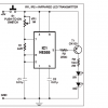
Parking sensor circuit mainly consists of two sections, one is transmitter section and the other is receiver section. The transmitter section uses NE555 timer IC as an astable multivibrator for driving the IR transmitter. The transmitter frequency is set to be 120Hz.
The IR pulses transmitted by the IR transmitter are reflected back because of the obstacle and received by the IR receiver.
The received signal is amplified by the U2:A. The output voltage of the Peak detector (R4 and c4) is proportional to the distance between car bumper and obstacle. The output voltage of the peak detector is given to the inputs of three comparators U2: B, U2: C and U2:D. These comparators switch the status LED’s according to the input voltage and the reference voltage.
Circuit design
In transmitter section, 555 timer is operated in astable mode to generate a signal with frequency of 120 Hz. The 4th pin of 555 timer is connected to supply to avoid sudden resets. The output pulse is produced at 3rd pin of 555 timer. Here resistors R1, R2 and C1 set the output frequency of 555 timer.
The received by the IR receiver is amplified the by the operational amplifier U2:A. Resistor R4 and C4 forms peak detector to detect peak of the amplified signal.
Op – amp as Comparator:
Op-amp has two inputs (non-inverting and inverting) and one output. The output of operational amplifier is high when non-inverting voltage is greater than inverting voltage.
The output voltage is low, when inverting voltage is greater than non-inverting voltage.
In the above circuit the voltages at non inverting pins of comparators acts as a reference voltage and inverting input voltages at comparators are compared with reference voltages to produce the output.
Here resistors R8 to R11 are used to set different reference voltages at their non inverting pins.
Resistors R12, R13 and R14 are used to protect the LED’s from high voltages.
Working
The distance between car and obstacle is understood by the group of LED’s (D5 to D7). If the distance between car and obstacle is 25cm then D7 will glow. At the distance of 20cm D7 and D6 LEDs turn ON and at a distance of 5cm all LED’s (D5, D6, D7) glow. When the distance is more than 25cm then all LED’s will turn off.
Applications
- This circuit can be used in auto mobiles to park the vehicle safely.
- We can use this circuit to measure the distance.
- We can also use this circuit as IR Liquid Level Detector by making few modifications.
Additional information
| Weight | 1.000000 kg |
|---|
Related products
-
- Out of StockRead more

-
-
- Out of StockRead more
- Mini Projects, NodeMcu Mini Projects
Air quality monitor
- Call for Price
-
-
- Out of StockRead more
- Mini Projects, NodeMcu Mini Projects
Smart security system with Voice
- Call for Price
-

Reviews
There are no reviews yet.