Programming the LaunchPad TMS320F28027F using Code Composer Studio
Steps to Program LaunchPad using CCS
☞Open Code Composer Studiov4, it will prompt for a workspace path, Select the matlab current folder path which contains simulink(.mdl) files.
☞Click Ok.
☞Click View in the menu –Choose Target Configurations.
☞Click Target in the menu – click New Target Configuration.
Choose the following settings
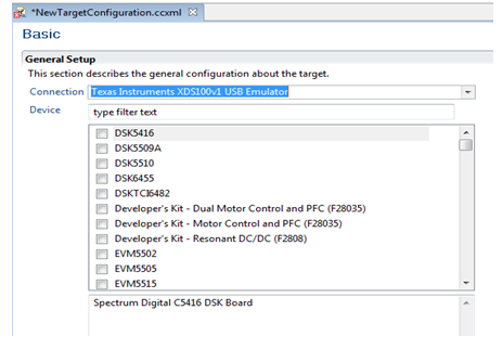
☞Connection – Texas Instruments XDS100v1 USB Emulator.
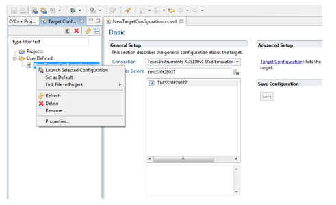
☞Device – TMS320F28027F.
☞Click Save.
☞Right click NewTargetConfiguration.ccxml – Set as Default
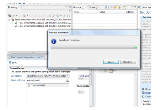
☞Right click NewTargetConfiguration.ccxml – Launch selected Configuration.
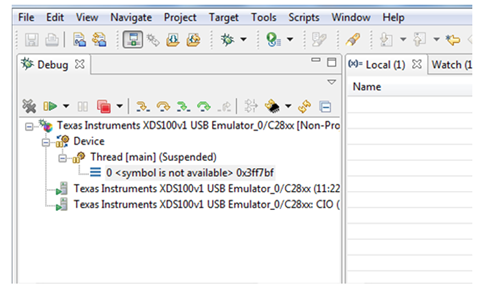
☞Right click Thread [main] (Disconnected (Unknown)) – Connect Target.
Note: Download the Code Composer Studio V4 in the following Link
http://processors.wiki.ti.com/index.php/Download_CCS
Screenshot to Select Emulator in CCS
1.Select Texas Instruments XDS100v1 USB Emulator in Connection drop down menu in the New Target Configuration settings as shown in the below figure
2.In Device tab, Select Processor Details as TMS320F28027F and Click Save.
3.Right Click on New Target Configuration – Choose Launch Selected Configuration
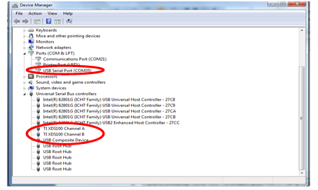
4.Now Connect the LaunchPad C2000 Piccolo TMS320F28027F to the PC USB port and drivers will be installed automatically. To verify the connection status follow the below steps.
Right click My Computer icon and select Device Manager
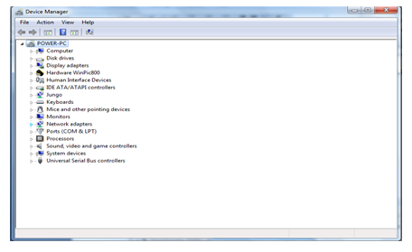
Expand universal Serial Bus Controllers and Ports (COM & LPT) and verify as per the below screenshot.
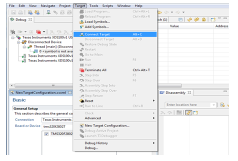
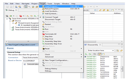
5.Click on Target – Select Connect Target as per the below screenshot
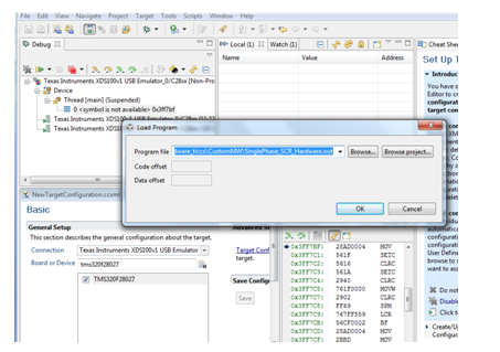
6.Click on Target – Select Load program
7.Choose file path from Matlab file location (filename.out) and click OK
(E.g.) C:\Users\pansys011\Desktop\Single Phase SCR – HalfWave\Single Phase SCR_Hardware\SinglePhase_SCR_Hardware_ticcs\CustomMW
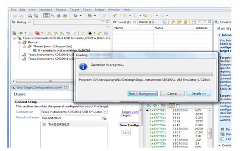
8.Once the program is loaded ,In Debug, Run the file
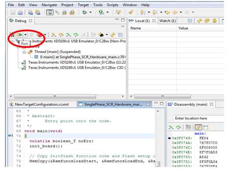
9.Check the hardware Pins GPIO0, GPIO1, GPIO2, and GPIO3 with respect to ground for PWM Pulses.
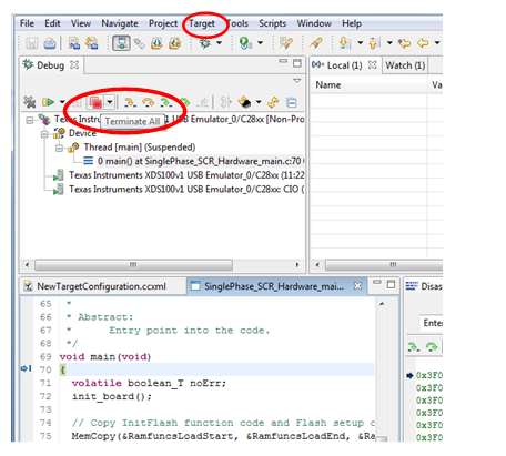
10.To disconnect the Controller from debug mode, click on Target and Terminate All as show in the figure.
11.Now Close CCSV4, Programming has been done successfully.