
How to Interface Stepper motor with 8051 Lab Trainer Kit
8051 – TRAINER BOARD
PS-TRAINER-8051 trainer kit is proposed to smooth the progress of learning and developing designs of MCU from Intel and NXP. It has the facility to connect PC’s 101/104 Keyboard, to enter user programs in Assembly languages. Serial communication achieved using 8051. It also supports C & assembly language in standalone kit (P89V51RD2). It’s designed as to facilitate On-board Programmer for NXP 8051 MCU through ISP on serial port.
STEPPER MOTOR
A stepper motor is a brushless, synchronous electric motor that converts digital pulses into mechanical shaft rotation. Every revolution of the stepper motor is divided into a discrete number of steps, and the motor must be sent a separate pulse for each step.
INTERFACING STEPPER MOTOR
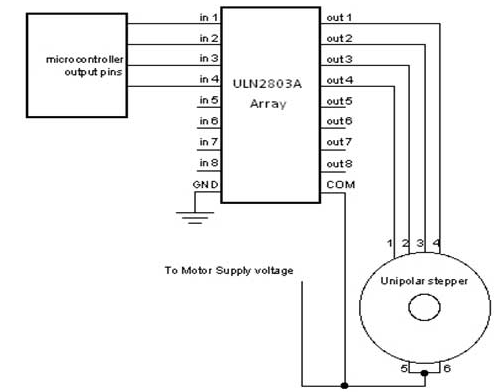
Fig. 1 shows how to interface the Stepper Motor to microcontroller. As you can see the stepper motor is connected with Microcontroller output port pins through a ULN2803A array. So when the microcontroller is giving pulses with particular frequency to ls293A, the motor is rotated in clockwise or anticlockwise.
INTERFACING STEPPER MOTOR WITH 8051
We now want to control a stepper motor in 8051 trainer kit. It works by turning ON & OFF a four I/O port lines generating at a particular frequency.
The 8051 trainer kit has three numbers of I/O port connectors, connected with I/O Port lines (P1.0 – P1.7),(p3.0 – p3.7) to rotate the stepper motor. Ls293d is used as a driver for port I/O lines, drivers output connected to stepper motor, connector provided for external power supply if needed.
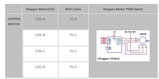
PIN ASSIGNMENT WITH 8051
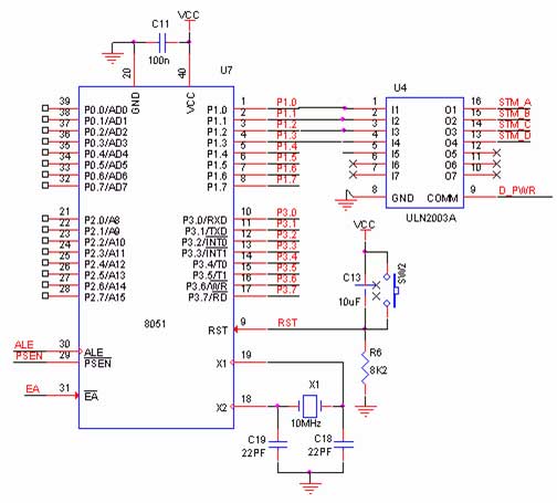
CIRCUIT DIAGRAM TO INTERFACE STEPPER MOTOR WITH 8051
ASSEMBLY PROGRAM TO RUN THE STEPPER MOTOR USING 8051
| ADDRESS | OP CODE | MNEMONICS | COMMENTS |
| 8500 | 74 80 | MOV A, #80H | Initialize 80HEX value to Accumulator |
| 8502 | 90 40 03 | MOV DPTR, #4003 | Move 4003 to R1 register |
| 8505 | F0 | MOVX @DPTR, A | Store ACC value into R1 register |
| 8506 | 90 40 00 | MOV DPTR, #4000 | Move 4000 to R1 register |
| 8509 | 74 66 | MOV A, #66H | Move 66HEX value to Accumulator |
| 850B | F0 | AGAIN:MOVX@DPTR, A | In AGAIN, Store ACC value into R1 |
| 850C | 03 | RR A | Rotate sequence for clockwise |
| 850D | B1 11 | ACALL DELAY | wait |
| 850F | 80 FA | SJMP AGAIN | Short Jump into AGAIN |
| 8511 | 7D 05 | DELAY: MOV R5, #5 | In DELAY, Load 5 value into R5 |
| 8513 | 7C 0F | H3: MOV R4, #0F | In H3, Load 0F value into R4 register |
| 8515 | 7B 43 | H2: MOV R3, #43 | In H2, Load 43 value into R3 register |
| 8517 | DB FE | H1 : DJNZ R3, H1 | H1, Decrement R0& check if it’s not 0 |
| 8519 | DC FA | DJNZ R4, H2 | Decrement R4& Check if it’s not 0 |
| 851B | DD F6 | DJNZ R5, H3 | Decrement R5& Check if it’s not 0 |
| 851D | 22 | RET | Return |
NOTE: To turn the motor in the reverse direction enter as (Rl A instead of RR A). The schematics sections given is, stepper motor connected to port 1 and the sample program is given based on 8255.


hello
wolud you help me write assmbly code to control stepper motor from matlab gui?