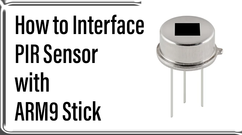
How to Interface PIR Sensor with ARM9 Stick
ARM9-LPC2929 STICK BOARD
The is specifically designed to help students to master the required skills in the area of embedded systems. The board is designed in such way that all the possible features of the microcontroller will be easily used by the students. The board supports Keil µVision 4 compilers with Keil ULink2.
NXP Microcontroller,ARM9-LPC2929 stick board is proposed to smooth the progress of developing and debugging of various designs encompassing of speed 32-bit Microcontrollers. It integrates CAN, LIN, UART, ADC, PWM, I2C, SPI, Timer, Interrupt etc., to create a stand-alone versatile test platform.
ARM9 Stick Board having more no of I/O line for user access able. Its consists of 64 GPIO pins, CAN0/1, LIN1, I2C0/1, UART0/1, SPI0/1, USB, ADC0/1/2, PWM, Timer and more features. Users can easily access the controller and develop more application by using
PIR Sensor
PIR is the abbreviation of Passive Infrared Sensor. All objects with a temperature above absolute zero emit heat energy in the form of radiation. Usually this radiation is invisible to the human eye because it radiates at infrared wavelengths, but it can be detected by electronic devices designed for such a purpose.
This is a simple to use motion sensor. Power it up and wait 1-2 seconds for the sensor to get a snapshot of the still room. If anything moves after that period, the ‘OUT’ pin will go low.
PROJECT DESCRIPTION
Connecting wires (Green Color wires):
The connecting wires are both sides having female type, because ARM9 stick, PIR sensor and LCD models are having male type connector for interfacing.
PIR Sensor Pin Details:
1. VCC – 3.3 V
2. OUT – Output of Sensor(Set this line as GPIO)
3. GND – GND (Set this line as GPIO or connect to Ground)
Details of LCD:
For PIR sensor output will get in 16×2 LCD.This LCD is configuring as 4 bit mode operation. For more details about interfacing with LCD, refer How articles for LCD Interfacing.
Output of PIR Sensor:
☞Motion: DETECTED (Its Shown in LCD)
☞Motion: NOT DTED (It’s shown in LCD)
Hardware’s:
☞ULink2 for Download program
☞PIR Sensor
☞USB Micro cable (for Stick board Power and UART)
☞USB Mini cable (for ULink2)
☞20 Pin FRC Cable (for interface Stick board and ULink)
☞Connecting Wires.
Software’s:
☞Keil UVision4
Functional Pin Diagram of ARM9 Stick Board

Front view of PIR Sensor

Rear view of PIR Sensor

Circuit for ARM9 Stick Interface With PIR Sensor_LCD

Real view 1 of ARM9 Stick Interface with PIR Sensor

Real view 2 of ARM9 Stick Interface with PIR Sensor

Output of PIR Sensor
1. When there is no motion detected
2. When there is motion detected

Downloading the Project file into Stick Board using Keil4

C Program for Interfacing PIR Sensor with ARM9 Stick Board
Title: Program PIR Sensor with ARM9
#include  //Register Description Header for LPC2929


#define RS 0x1 // Register Select

#define RW 0x2 // Read Write Select

#define EN 0x4 // Enable


#define D7 0x800 // Data Line 7

#define D6 0x400 // Data Line 6

#define D5 0x200 // Data Line 5

#define D4 0x100 // Data Line 4


#define A 0x2000 // LCD Anode

#define K 0x4000 // LCD Cathode

#define CST 0x8000 // LCD Contrast


#define PIR_OUT 0x40 // PIR Out

#define PIR_GND 0x20 // PIR Ground


void lcd_cmd (char);

void lcd_data (char);

void lcd_initialize (void);

void lcd_display (void);

void LCD4_Convert(char);


char cmd[] = {0x33,0x32,0x28,0x0C,0x06,0x01}; // LCD Comments

char msg[] = {" PIR SENSOR OUT "}; // First Line of LCD

char msg1[]= {"MOTION:"}; // Second Line of LCD


char msg2[]= {"DETECTED"}; // Output status of LCD

char msg3[]= {"NOT DETD"}; // Output status of LCD


int main(void) // Main Function


{

int i;

GPIO3_DR |= 0xFFFF; // P3.0 to P3.15 config as Out Direction

GPIO1_DR |= PIR_GND; // PIR_GND config as Out Direction

GPIO1_DR &= ~PIR_OUT; // PIR_OUT config as In Direction

SFSP1_6 = 0xC; // PIR_OUT config as Dig In with int PU


GPIO3_OR |= A; // Set Anode as High

GPIO3_OR &= ~(CST | K ); // Set CST & Cathode as Low

GPIO1_OR &= ~PIR_GND; // Set PIR_GND as Low


lcd_initialize(); // LCD Initialize

lcd_display(); // Display Char in LCD


while(1)

{

if(GPIO1_PINS & PIR_OUT) // Read PIR Sensor Output

{

lcd_cmd(0xc7); // command for start line

for(i=0;msg2[i]!='\0';i++)

{

lcd_data(msg2[i]);

}

}

else

{

lcd_cmd(0xc7); // command for start line

for(i=0;msg1[i]!='\0';i++)

{

lcd_data(msg3[i]);

}

}

}

}

void delay(int n) // Delay function

{

unsigned int i,j;

for(i=0;i