How to Interface LED with 8051 Lab Trainer Kit
8051 – TRAINER BOARD
PS-TRAINER-8051 trainer kit is proposed to smooth the progress of learning and developing designs of MCU from Intel and NXP. It has facility to connect PC’s 101/104 Keyboard, to enter user programs in Assembly languages. Serial communication achieved using 8051. It also supports C & assembly language in standalone kit (P89V51RD2). It’s designed as to facilitate On-board Programmer for NXP 8051 MCU through ISP on serial port.
LED (LIGHT EMITTING DIODE)
Light Emitting Diodes (LED) is the most commonly used components, usually for displaying pins digital states. Typical uses of LEDs include alarm devices, timers and confirmation of user input such as a mouse click or keystroke.
INTERFACING LED
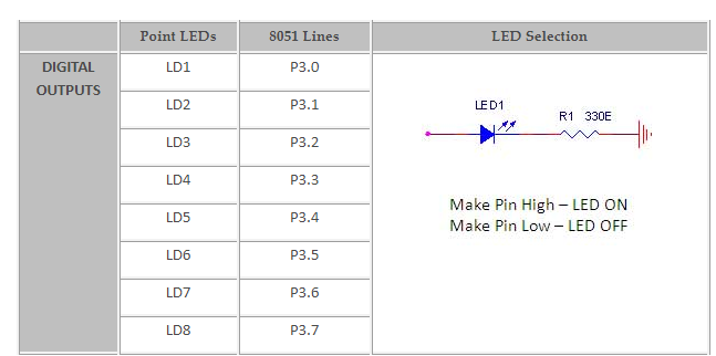
Fig. 1 shows how to interface the LED to microcontroller. As you can see the Anode is connected through a resistor to GND & the Cathode is connected to the Microcontroller pin. So when the Port Pin is HIGH the LED is OFF & when the Port Pin is LOW the LED is turned ON.

INTERFACING LED WITH 8051
LED in 8051 Trainer Board works by turning ON a LED & then turning it OFF & then looping back to START. However the operating speed of microcontroller is very high so the flashing frequency will also be very fast to be detected by human eye.
PIN ASSIGNMENT WITH 8051
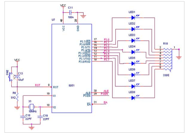
CIRCUIT DIAGRAM TO INTERFACE LED WITH 8051
ASSEMBLY PROGRAM TO ON AND OFF LED USING 8051
| MEMORY ADDRESS | OPCODE | MNEMONICS |
| 9100 | 74 55 | L1:MOV A,#FF |
| 9102 | 7C | MOV B0,A |
| 9104 | 12 91 0F | LCALL DELAY |
| 9107 | 74 00 | MOV A,#00 |
| 9109 | 7C | MOV B0,A |
| 910b | 12 91 0F | LCALL DELAY |
| 910D | 80 F9 | SJMP L1 |
| 910F | 7D 05 | DELAY: MOV R5,#05 |
| 9111 | 7C FF | H3 MOV R4,#FF |
| 9113 | 7B FF | H2 MOV R3,#FF |
| 9115 | DB FE | H1: DJNZ R3,H1 |
| 9117 | DC FA | DJNZ R4,H2 |
| 9119 | DD F6 | DJNZ R5,H3 |
| 911B | 22 | RET |