How to Interface LCD with MSP430F5529 MSP430 Development Board
The MSP430 Development kit is specifically designed to help students to master the required skills in the area of embedded systems. The kit is designed in such way that all the possible features of the microcontroller will be easily used by the students. The kit supports with Code Composer Studio v4 and later through USB port.
Texas Instrument Microcontroller, MSP430 Development kit is proposed to smooth the progress of developing and debugging of various designs encompassing of speed 16-bit Microcontrollers. It integrates on board PS2, UART, ADC, PWM, Temperature Sensor, Relay, Buzzer, I2c Seven Segment, I2C Serial EEPROM, Temperature Sensor LM35, Matrix Keypad, Switch, LED, Stepper Motor Driver, Traffic Light Controller, I2C RTC, LCD & GLCD Display to create a stand-alone versatile test platform. User can easily engage in Development in this platform, or use it as reference to application Development.
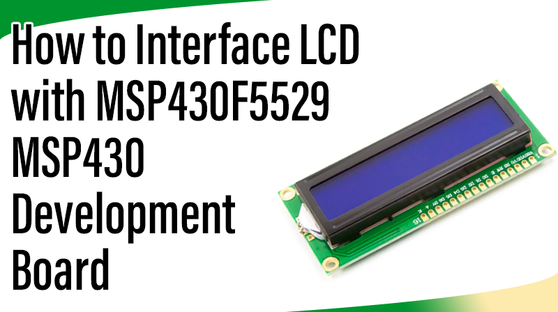
LCD (Liquid Crystal Display)
Liquid Crystal Display also called as LCD is very helpful in providing user interface as well as for debugging purpose. A liquid crystal display (LCD) is a flat panel display that uses the light modulating properties of liquid crystals (LCs). LCD Modules can present textual information to user.
Interfacing LCD with MSP430F5529
Fig. 1 shows how to interface the LCD to microcontroller. The 2×16 character LCD interface card with supports both modes 4-bit and 8-bit interface, and also facility to adjust contrast through trim pot.
In 4-bit interface 7 lines needed to create 4-bit interface; 4 data bits (D0 – D3), three control lines, address bit (RS), read/write bit (R/W) and control signal (E).
In 8-bit interface 11 lines needed to create 8-bit interface; 8 data bits (D0 – D7), three control lines, address bit (RS), read/write bit (R/W) and control signal (E).
We now want to display a text in MSP430F5529 Development Board by using 4 bit LCD module. The MSP430F5529 Development Board has 16 pin strip connector for LCD connections.
Pin Assignment with MSP430F5529
Circuit Diagram to Interface 4 bit LCD with MSP430F5529
C Program to display a text in LCD using MSP430F5529
***************************************************************************************
Title : Program to 4 bit LCD display
***************************************************************************************
#include
#include
void LCD_init(void);
void DelayMs(int Ms);
void LCD_cmd4(unsigned char cmd);
void LCD_dat4(unsigned char byte);
unsigned char i;
const unsigned char Msg1[] = " 16x2 LCD Test... ";
const unsigned char Msg2[] = " F2812 EVB BOARD ";
void main()
{

WDTCTL = WDTPW + WDTHOLD;

//

Stop watchdog timer P7DIR = 0xF0;
// Set P7.4-P7.7 to Output direction P5DIR = 0xC0;
P4DIR = 0x80;
DelayMs(100);
LCD_init();
DelayMs(50);
while(1)
{
LCD_cmd4(0x80);
for(i=0;i<16;i++)
{
LCD_dat4(Msg1[i]);
DelayMs(5);
}

LCD_cmd4(0xc0);
for(i=0;i<16;i++)
{
LCD_dat4(Msg2[i]);
DelayMs(5);
}
}
}

void LCD_init(void)
{
LCD_cmd4(0x33);
LCD_cmd4(0x22);
LCD_cmd4(0x22);
LCD(0x22);
LCD_cmd4(0x28);

// 28 for four bit mode LCD_cmd4(0x0c);

LCD_cmd4(0x06); LCD_cmd4(0x01);
}
void LCD_cmd4(unsigned char cmd)
{

P5OUT = 0x00;

// RW=0,RS=0 P7OUT = cmd;
P4OUT = 0x80;
// En = 1;

P4OUT = 0x00;

// En = 0;
cmd = (cmd<<4) & 0xF0;
P7OUT = cmd;
P4OUT = 0x80;

// En = 1;

P4OUT = 0x00; // En = 0;
DelayMs(3);
}
void LCD_dat4(unsigned char byte)
{
P5OUT = 0x80;
// RW=0,RS=0 P7OUT = byte; P4OUT = 0x80;
// En = 1;
P4OUT = 0x00;

// En = 0;

byte = (byte<<4) & 0xF0;
P7OUT = byte;
P4OUT = 0x80;
// En = 1;
P4OUT = 0x00;
// En = 0;
DelayMs(3);

}
void DelayMs(int Ms)
{
int i; while(Ms>0)
{
for(i=0;i<104;i++);
Ms--;
}
}