How to Interface Keypad with ARM9 Stick Board
ARM9-LPC2929 STICK BOARD
The is specifically designed to help students to master the required skills in the area of embedded systems. The board is designed in such way that all the possible features of the microcontroller will be easily used by the students. The board supports Keil µVision 4 compilers with Keil ULink2.
NXP Microcontroller,ARM9-LPC2929 stick boardis proposed to smooth the progress of developing and debugging of various designs encompassing of speed 32-bit Microcontrollers. It integrates CAN, LIN, UART, ADC, PWM, I2C, SPI, Timer, Interrupt etc., to create a stand-alone versatile test platform.
ARM9 Stick Board having more no of I/O line for user access able. Its consists of 64 GPIO pins, CAN0/1, LIN1, I2C0/1, UART0/1, SPI0/1, USB, ADC0/1/2, PWM, Timer and more features. Users can easily access the controller and develop more application by using
Keypad
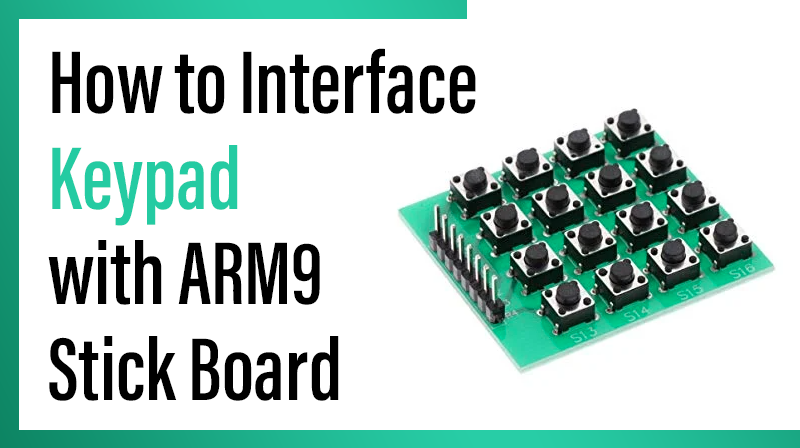
A keypad is a set of buttons arranged in a block or “pad” which usually bear digits, symbols and usually a complete set of alphabetical letters. If it mostly contains numbers then it can also be called a numeric keypad. Here we are using 4 X 4 matrix keypad.
Interfacing keypad
Fig. 1 shows how to interface the 4 X 4 matrix keypad to two ports in microcontroller. The rows are connected to an output port and the columns are connected to an input port.
To detect a pressed key, the microcontroller grounds all rows by providing 0 to the output latch, and then it reads the columns. If the data read from the columns is D3-D0=1111, no key has been pressed and the process continues until a key press is detected. However, if one of the column bits has a zero, this means that a key press has occurred. For example, if D3-D0=1101, this means that a key in the D1 column has been pressed.
After a key press is detected, the microcontroller will go through the process of identifying the key. Starting with the top row, the microcontroller grounds it by providing a low to row D0 only; then it reads the columns.
If the data read is all 1s, no key in that row is activated and the process is moved to the next row. It grounds the next row, reads the columns, and checks for any zero. This process continues until the row is identified. After identification of the row in which the key has been pressed, the next task is to find out which column the pressed key belongs to.
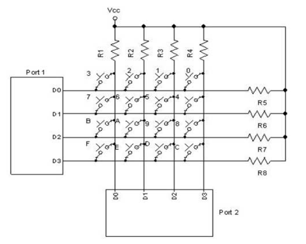
Fig. 1 Interfacing keypad to Microcontroller
Interfacing keypad with ARM9 Stick Board
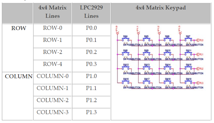
Now we want to scan a keypad in ARM9 Stick Board. In case of 4X4 matrix Keypad both the ends of switches are connected to the port pin i.e. four rows and four columns. So in all sixteen switches have been interfaced using just eight lines.
1Keypads arranged by matrix format, each row and column section pulled by high or low by , all row lines(P0.0 – P0.3) and column lines(P1.0 to P1.3) connected directly by the port pins.
Pin Assignment with LPC2929
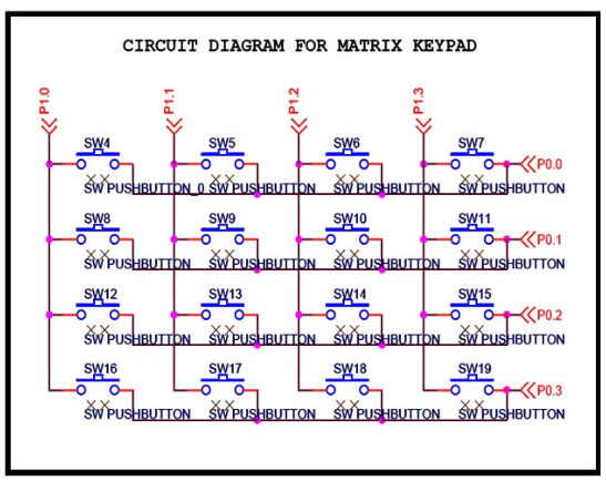
Circuit Diagram for Interface keypad with ARM9 Stick Board
Circuit Diagram for Matrix Keypad Output
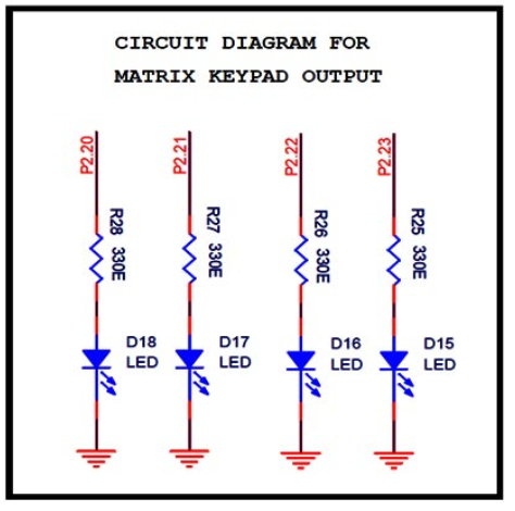
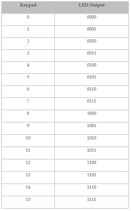
Output
C Program for Matrix keypad interfacing with ARM9 Stick Board
Title : Program to keypad interfacing
#include

#include


int a,b,Row,Col;

int array[4][4] = {0x0,0x1,0x2,0x3,0x4,0x5,0x6,0x7,0x8,0x9,0xA,0xB,0xC,0xD,0xE,0xF};

int main(void)

{

SFSP0_0 = 0xC;SFSP0_1 = 0xC;SFSP0_2 = 0xC;SFSP0_3 = 0xC;

// Digital In no PU & PD and fn 0

SFSP1_0 = 0xC;SFSP1_1 = 0xC;SFSP1_2 = 0xC;SFSP1_3 = 0xC; // Digital In no PU & PD and fn 0

GPIO2_DR = 0xF00000; // Set as direction port


while(1)

{

GPIO0_DR = 0x0; // Set Row as input direction

GPIO1_DR = 0xF; // Set coloum as output direction

GPIO1_OR = 0x0; // Set as coloum as Low

a = GPIO0_PINS;

a = a & 0xF;

switch(a)

{

case 0xE:

Row = 0;

GPIO0_DR = 0xF; GPIO1_DR = 0x0;

// Set Coloum as input & Row as output direction

b = GPIO1_PINS & 0xF;

GPIO0_OR =0x0;

switch(b)

{

case 0xE:

Col = 0;

GPIO2_OR = ((array[Row][Col])<<20);

break;


case 0xD:

Col = 1;

GPIO2_OR = ((array[Row][Col])<<20);

break;


case 0xB:

Col = 2;

GPIO2_OR = ((array[Row][Col])<<20);

break;


case 0x7:

Col = 3;

GPIO2_OR = ((array[Row][Col])<<20);

break;

}

break;


case 0xD:

Row = 1;

GPIO0_DR = 0xF;

GPIO1_DR = 0x0;

GPIO0_OR =0x0;

b = GPIO1_PINS & 0xF;


switch(b)

{

case 0xE:

Col = 0;

GPIO2_OR = ((array[Row][Col])<<20);

break;


case 0xD:

Col = 1;

GPIO2_OR = ((array[Row][Col])<<20);

break;


case 0xB:

Col = 2;

GPIO2_OR = ((array[Row][Col])<<20);

break;


case 0x7:

Col = 3;

GPIO2_OR = ((array[Row][Col])<<20);

break;

}

break;


case 0xB:

Row = 2;

GPIO0_DR = 0xF;

GPIO1_DR = 0x0;

GPIO0_OR =0x0;

b = GPIO1_PINS & 0xF;


switch(b)


{

case 0xE:

Col = 0;

GPIO2_OR = ((array[Row][Col])<<20);

break;


case 0xD:

Col = 1;

GPIO2_OR = ((array[Row][Col])<<20);

break;


case 0xB:

Col = 2;

GPIO2_OR = ((array[Row][Col])<<20);

break;


case 0x7:

Col = 3;

GPIO2_OR = ((array[Row][Col])<<20);

break;

}

break;


case 0x7:

Row = 3;

GPIO0_DR = 0xF;

GPIO1_DR = 0x0;

GPIO0_OR =0x0;

b = GPIO1_PINS & 0xF;


switch(b)

{

case 0xE:

Col = 0;

GPIO2_OR = ((array[Row][Col])<<20);

break;


case 0xD:

Col = 1;

GPIO2_OR = ((array[Row][Col])<<20);

break;


case 0xB:

Col = 2;

GPIO2_OR = ((array[Row][Col])<<20);

break;


case 0x7:

Col = 3;

GPIO2_OR = ((array[Row][Col])<<20);

break;

}

break;


default:

GPIO2_OR = 0x0;

break;

}

}

}