How to Interface I2C-RTC with PIC16F877A PIC Advanced Development Board
PIC16F/18F Advanced Development Board is specifically designed to help students to master the required skills in the area of embedded systems. The kit is designed in such way that all the possible features of the microcontroller will be easily used by the students. The kit supports in system programming (ISP) which is done through USB port.
Microchip’s PIC (PIC16F877A), PIC16F/18F Advanced Development Kit is proposed to smooth the progress of developing and debugging of various designs encompassing of High speed 8-bit Microcontrollers
I2C (Inter Integrated Circuit)
The I2C (Inter-IC) bus is a bi-directional two-wire serial bus that provides a communication link between integrated circuits (ICs).I2C is a synchronous protocol that allows a master device to initiate communication with a slave device. Data is exchanged between these devices.
RTC (Real Time Clock)
The DS1307 Serial Real-Time Clock is a low-power; full binary-coded decimal (BCD) clock/calendar plus 56 bytes of NV SRAM. Address and data are transferred serially via a 2-wire, bi-directional bus. The clock/calendar provides seconds, minutes, hours, day, date, month, and year information. The end of the month date is automatically adjusted for months with fewer than 31 days, including corrections for leap year. The clock operates in either the 24-hour or 12-hour format with AM/PM indicator.
Interfacing I2C – RTC
Fig. 1 shows how to interface the EEPROM with microcontroller through I2C. I2C is a Master-Slave protocol. I2C has a clock pulse along with the data. The master device controls the clock line, SCL. This line dictates the timing of all transfers on the I2C bus. No data will be transferred unless the clock is manipulated.
I2c bus supports many devices, each device is recognized by a unique address—whether it’s a micro-controller, LCD Driver, memory or keyboard interface and can operate as transmitter or receiver based on the functioning of the device. The controller designed controls the RTC ds1307 device through I2C protocol. The I2C Controller here acts as a master device and controls RTC ds1307 which acts as a slave. The read operation is accomplished by sending a set of control signals including the address and/or data bits. The control signals must be accompanied with proper clock signals.
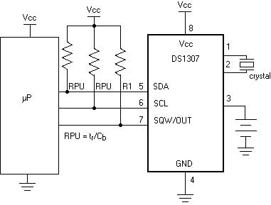
Fig. 1 Interfacing I2C – RTC to Microcontroller
Interfacing I2C – RTC with PIC16F877A
We now want to read date & time by using I2C – RTC in PIC16F/18F Advanced Development Board. Wiring up an I2C based RTC to the I2C port is relatively simple. The RTC also makes the software easier as it takes care of all calendar functions; accounting for leap years etc. The DS1307 (RTC) Real Time Clock IC (an I2C real time clock) is an 8 pin device using an I2C interface.
In PIC16F/18F Advanced Development Kit, 2 nos. of RTC lines are controlled by I2C Enabled drivers. I2C Lines serial clock of CLK (RC3), serial data of DATA (RC4) connected to the I2C based serial RTC ds1307 IC. The date & times are read in PIC16F/18F Advanced Development Kit by using these DATA & CLK I2C lines.
Pin Assignment with PIC16F877A
Circuit Diagram to Interface I2C–RTC with PIC16F
Source Code
The Interfacing I2C – RTC with PIC16F877A program is very simple and straight forward that read date & time in RTC by using I2C & the value is displayed in serial port. A delay is occurring in every single data read from RTC. The delay depends on compiler how it optimizes the loops as soon as you make changes in the options the delay changes.
C Program to interface I2C – RTC with PIC16F
#include
//Define PIC Registers #include
__CONFIG(0x3f72);
//Select HS oscillator, Enable (PWRTE,BOREN),
//Disable (CPD,CP,WDTEN,In-circuit Debugger)
#define LC01CTRLIN 0xd0
#define LC01CTRLOUT 0xd1
#define I2C_FREG 100
#define FOSC 10000
#define BAUD_RATE 9.6
// 9600 Baud rate #define BAUD_VAL (char)(FOSC/ (16 * BAUD_RATE )) - 1;
//Calculation For 9600 Baudrate @10Mhz unsigned char sec,min,hour,day,date,month,year; unsigned char data[7]={0x45,0x59,0x71,0x04,0x05,0x10,0x06};
int i;
void DS1307Write(unsigned char,unsigned char);
void WaitMSSP();
unsigned char DS1307Read(unsigned char);
void i2c_init(void);
void ds1307_init(void);
void serial_init(void);
void DelayMs(unsigned int);
void main()
{
int count=0;
DelayMs(20);
ds1307_init();
serial_init();
for(i=0;i<7;i++) DS1307Write(i,data[i]);
printf("\033[2J");
DelayMs(20);
while(1)
{
sec=DS1307Read(0);
// Read second min=DS1307Read(1);
// Read minute hour=DS1307Read(2);
// Read hour day=DS1307Read(3);
// Read day date=DS1307Read(4);
// Read date month=DS1307Read(5);
// Read month year=DS1307Read(6);
// Read year printf("Time: %x : %x : %x ",(hour&0x1f),min,sec);
//Display the Hours, Minutes, Seconds(hours is taken from 5 LSB bits printf("Date: %x / %x / %x \r",date,month,year);
//Display the Date, Month, Year DelayMs(150);
}
}
void DS1307Write(unsigned char addr, unsigned char data)
{
SEN=1;
//Initiate Start condition on SDA & SCL pins WaitMSSP();
SSPBUF=LC01CTRLIN;
// Slave address + Write command WaitMSSP();
SSPBUF=addr;
// Write the location WaitMSSP();
SSPBUF=data;
// Write the Data WaitMSSP();
PEN=1;
// Enable the Stop bit WaitMSSP();
}
unsigned char DS1307Read(unsigned char addr)
{
unsigned char x;
RSEN=1;
// Enable the repeated Start Condition WaitMSSP ();
SSPBUF=LC01CTRLIN;
// Slave address + Write command WaitMSSP ();
SSPBUF=addr;
//Write the location (memory address of Hour, minute, etc... WaitMSSP ();
RSEN=1;
// Enable the repeated Start Condition WaitMSSP ();
SSPBUF=LC01CTRLOUT;
// Slave address + Read command WaitMSSP ();
RCEN=1;
// Enable to receive data WaitMSSP ();
ACKDT=1;
// Acknowledge the operation (Send NACK) ACKEN=1;
// Acknowledge sequence on SDA & SCL pins PEN=1;
// Enable the Stop bit WaitMSSP ();
x=SSPBUF;
// Store the Receive value in a variable return (x);
}
void WaitMSSP()
{
while(!SSPIF);
// SSPIF is zero while TXion is progress SSPIF=0;
}
void ds1307_init()
{
TRISC3=1;
// RC3,RC4 set to I2C Mode(Input) TRISC4=1;
SSPCON=0x28;
// Enable the SDA,SCL & I2C Master Mode SSPADD=(FOSC / (4 * I2C_FREG)) - 1;
// SSP baud rate 100Khz SSPSTAT=0x80;
// Disable slew Rate control PORTC=0x18;
DS1307Write(0,0x00);
}
void serial_init()
{
TRISC6=1;
// RC7, RC6 set to USART Mode TRISC7=1;
TXSTA=0x24;
// Enable Transmission, Asynchronous mode, High Speed mode SPBRG=BAUD_VAL;
// 9600 Baud rate selection RCSTA=0x90;
// Enable Serial Port & Continuous Reception TXIF=1;
// Enable Transmission
}
void putch(unsigned char byte)
//Required for printf statement
{
while(!TXIF);
// Wait for the Transmit Buffer to be empty TXREG = byte;
// Transmit the Data
}
void DelayMs(unsigned int Ms)
{
int delay_cnst;
while(Ms>0)
{
Ms--;
for(delay_cnst = 0;delay_cnst <220;delay_cnst++);
}
}
To compile the above C code you need the Mplab software & Hi-Tech Compiler. They must be properly set up and a project with correct settings must be created in order to compile the code. To compile the above code, the C file must be added to the project.
In Mplab, you want to develop or debug the project without any hardware setup. You must compile the code for generating HEX file. In debugging Mode, you want to check the port output without PIC16F/18F Advanced Development Board.
The PICKIT2 software is used to download the hex file into your microcontroller IC PIC16F877A through USB port.
Testing the I2C – RTC with PIC16F/18F
Give +12V power supply to PIC16F/18F Advanced Development .The RTC Battery device is connected with the PIC16F/18F Advanced Development. First check the entire Battery device fixed properly. A serial cable is connected between the microcontroller and PC.
In PC, open the Hyper Terminal for displaying the values from RTC.Now, the Hyper Terminal shows the received data from RTC Battery through I2C.If the Hyper Terminal is working but it is not reading any value from PIC16F/18F Advanced Development, then you just check the jumper connections. Change the Battery & ds1307 device.
If you are not receiving any data in Hyper Terminal, then you just check the serial cable is working or not. Otherwise you just check the code with debugging mode in Mplab. If you want to see more details about debugging just see the videos in below link.
General Information
- For proper working use the components of exact values as shown in Circuit file. Wherever possible use new components.
- Solder everything in a clean way. A major problem arises due to improper soldering, solder jumps and loose joints. Use the exact value crystal shown in schematic.