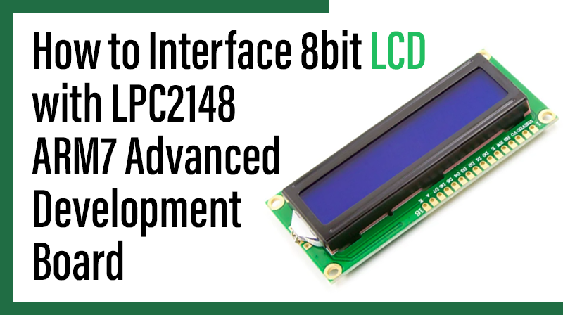
How to Interface 8bit LCD with LPC2148 – ARM7 Advanced development board
The ARM7 LPC2148 Advanced Development Board is specifically designed to help students to master the required skills in the area of embedded systems. The kit is designed in such way that all the possible features of the microcontroller will be easily used by the students. The kit supports in system programming (ISP) which is done through serial port.
NXP’s ARM7 (LPC2148), ARM Advanced Development Board Kit is proposed to smooth the progress of developing and debugging of various designs encompassing of High speed 32-bit Microcontrollers.
LCD (Liquid Crystal Display)
Liquid Crystal Display also called as LCD is very helpful in providing user interface as well as for debugging purpose. A liquid crystal display (LCD) is a flat panel display that uses the light modulating properties of liquid crystals (LCs). LCD Modules can present textual information to user.
Interfacing LCD
Fig. 1 shows how to interface the LCD to microcontroller. The 2×16 character LCD interface card with supports both modes 4-bit and 8-bit interface, and also facility to adjust contrast through trim pot. In 8-bit interface 11 lines needed to create 8-bit LCD display; 8 data bits (D0 – D7), three control lines, address bit (RS), read/write bit (R/W) and control signal (E).

Interfacing 8 bit LCD with LPC2148 – ARM7 Advanced Development Board
Display a text in LPC2148 Advanced Development Board by using 8 bit LCD module.
The ARM7 LPC2148 Advanced Development Board has seven numbers of LCD connections are needed to create 8-bit interface; connected with 8 data bits (P0.0 – P0.7, D0-D7), address bit (RS-P0.12), read/write bit (R/W-P0.13) and control signal (E-P0.14) to make LCD display.
Pin Assignment with LPC2148
Circuit Diagram to Interface 8 bit LCD with LPC2148 -ARM7 Advanced Development Board

Source Code
The Interfacing 8 bit LCD with LPC2148 program is very simple and straight forward, which display a text in 2 X 16 LCD module using 4 data lines only. Some delay is occurring when a single command / data is executed. The C programs are written in Keil software.
C Program to display a text in 8 bit LCD using LPC2148 -ARM7 Advanced Development Board
#include
#include
#include "LCD8.H"
void main()
{
PINSEL0 |= 0x05;
PINSEL1 = 0;
LCD_Config (&IOPIN0, 16);
while(1)
//Loop From Here....
{
Delay();
Delay();
lcd_cmd (&IOPIN0,16, 0x01);
Delay();
lcd_data (&IOPIN0,16,’1’);
}
}
void delay(unsigned int n)
{
unsigned int i,j;
for(i=0;i<n;i++)
for(j=0;j<12000;j++);
}
To compile the above C code you need the KEIL software. They must be properly set up and a project with correct settings must be created in order to compile the code. To compile the above code, the C file must be added to the project.
In KEIL, you want to develop or debug the project without any hardware setup. You must compile the code for generating HEX file. In debugging Mode, you want to check the port output without microcontroller Board.
The Flash Magic software is used to download the hex file into your microcontroller through UART0.
Testing the LCD Module with LPC2148
Give +3.3V power supply to LPC2148 Advanced Development Board; the LCD is connected with microcontroller LPC2148 Advanced Development Board. When the program is downloading into LPC2148 in Advanced Development Board, the screen should show the text messages.
If you not reading any text from LCD, then you just check the jumper connections & adjust the trim pot level. Otherwise, you just check it with debugging mode in KEIL. If you want to see more details about debugging just see the videos in the below link. How to Create and Debug a Project in Keil
General Information
- For proper working use the components of exact values as shown in Circuit file. Wherever possible use new components.
- Solder everything in a clean way. A major problem arises due to improper soldering, solder jumps, and loose joints.
- Use the exact value crystal shown in schematic.
- More instructions are available in the following articles,