

Line follower Robot
Call for Price
Line follower is an autonomous robot which follows either black line in white are or white line in black area. Robot must be able to detect particular line and keep following it.
Description
What is Line follower robot
Line follower is an autonomous robot which follows either black line in white are or white line in black area. Robot must be able to detect particular line and keep following it.
For special situations such as cross overs where robot can have more than one path which can be followed, predefined path must be followed by the robot.
In the following section, we will discuss the Line follower robot which follows black line in white area and take right turn whenever cross overs or Y shaped turn arrives.

Basics of Line follower robot
Input: Read the white/black on the floor and condition the input signal(s) for transmission into the microcontroller in a way that questions can be asked and decisions made.
Process: Based on the inputs received, microcontroller decide what change (if any) needs to be made to the robots speed and direction. Convert the results of any decisions made into something that can be sent to motor speed control and/or steering.
Output: Send the old or the newly adjusted control signals to speed and/or steering devices.
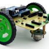
Materials used
☞Robo Car
☞Arduino Uno
☞Line following sensor
Basic Block diagram of Line follower robot

Input Sensor Selection
QRD1114 Optical Sensor is used a line sensor

Schematics for Constructing a line follower sensor

On the left side, the phototransistor acts as a voltage divider. (It is difficult to see in this figure, but there is a “C” for Collector and an “E” for Emitter on the top and bottom phototransistor leads.) The light reflected back from the floor will hit the base of the transistor, and instead of a base bias voltage being used to control current flow, the amount of light on the base determines current flow. At the extremes:
With no light on the base of the transistor, there is no current flow and it acts like an open switch. With no current flow, a voltmeter put on the output, labeled RA1 in the schematic, would read 5 Volts.
With maximum light on the phototransistor base, the transistor goes into saturation, acting like a closed switch, allowing current to flow from ground, through the phototransistor and resistor. The output will now read 0.0 Volts, since the “shorted switch” makes the output seem to be at the same potential as ground.
And at different light levels, we would expect the output voltage at RA1 to vary between 0 and 5 volts, depending on the light received by the base of the phototransistor.
Connection Circuit diagram with Arduino and Line follower sensor

Connection Circuit diagram with Motor

Arduino source code for Line follower robot
// Pantech Line Follower Robot Project //
// Sensor : QRD1114D //
// Powerd by Pantech Prolabs India Pvt Ltd //

#define REF 200
const int MotR_A = 3; // DC Motor1 Pole_A
const int MotR_B = 5; // DC Motor1 Pole_B
const int MotL_A = 6; // DC Motor2 Pole_A
const int MotL_B = 9; // DC Motor2 Pole_B
unsigned int Flag1,Flag2,Flag3,Flag4,Val;
void setup()
{
Serial.begin(9600);
pinMode(MotR_A, OUTPUT);
pinMode(MotR_B, OUTPUT);
pinMode(MotL_A, OUTPUT);
pinMode(MotL_B, OUTPUT);
}
void loop()
{
int sen1 = analogRead(A0);
int sen2 = analogRead(A1);
int sen3 = analogRead(A2);
int sen4 = analogRead(A3);
if (sen1>REF)
{ Flag1 = 1; }
else
{ Flag1 = 0; }
if (sen2>REF)
{ Flag2 = 1; }
else
{ Flag2 = 0; }
if (sen3>REF)
{ Flag3 = 1; }
else
{ Flag3 = 0; }
if (sen4>REF)
{ Flag4 = 1; }
else
{ Flag4 = 0; }
Val = (Flag1 | (Flag2<<1) | (Flag3<<2) | (Flag4<<3) );
Serial.print(Val);
Serial.println();
switch (Val)
{
case 0:
Robo_Right();
break;
case 1:
Robo_Left();
break;
case 3:
Robo_Left();
break;
case 6:
Robo_Front();
break;
case 7:
Robo_Left();
break;
case 8:
Robo_Right();
break;
case 12:
Robo_Right();
break;
case 14:
Robo_Right();
break;
case 15:
Robo_Front();
break;
default:
break;
}
}
void Robo_Front()
{
digitalWrite(MotR_A, LOW);
digitalWrite(MotR_B, HIGH);
digitalWrite(MotL_B, LOW);
digitalWrite(MotL_A, HIGH);
}
void Robo_Back()
{
digitalWrite(MotR_A, HIGH);
digitalWrite(MotR_B, LOW);
digitalWrite(MotL_B, HIGH);
digitalWrite(MotL_A, LOW);
}
void Robo_Right()
{
digitalWrite(MotR_A, HIGH);
digitalWrite(MotR_B, LOW);
digitalWrite(MotL_B, LOW);
digitalWrite(MotL_A, HIGH);
}
void Robo_Left()
{
digitalWrite(MotR_A, LOW);
digitalWrite(MotR_B, HIGH);
digitalWrite(MotL_B, HIGH);
digitalWrite(MotL_A, LOW);
}
void Robo_Stop()
{
digitalWrite(MotR_A, LOW);
digitalWrite(MotR_B, LOW);
digitalWrite(MotL_B, LOW);
digitalWrite(MotL_A, LOW);
}
Advantages of Line follower robot
☞Robot movement is automatic.
☞Used for long distance applications.
☞Used in home, industrial automation and Health Care.
☞Cost effective.
☞Simplicity of building.
Disadvantages of Line follower robot
☞Line follower robot follows a black line about 1 or 2 inches in width on a white surface.
☞Line tracing robots are simple robots with an additional sensors placed on them.
☞It always needs a path to run either white or black since the IR rays should reflect from the particular path.
☞Slow speed and instability on different line thickness or hard angles.
Applications of Line follower robot
☞Guidance system for industrial robots moving on shop floor etc.
☞Healthcare applications
☞Industrial applications.
☞Home applications.
Line follower robot Demo Video
Additional information
| Weight | 0.100000 kg |
|---|
Related products
-
- Read more

- Projects, Robotics Projects
Human Follower Smart Trolley
- Call for Price
-
-
Sale!
Add to cart

- Raspberry Pi Projects, Robotics Projects, Trending Projects
SLAM Robot
- ₹29,498.00 Exc Tax
-

-
Sale!
Reviews
There are no reviews yet.