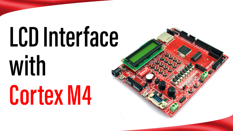
LCD Interface with Cortex M4
This example describes how to display a string in LCD using 4 bit mode
Procedure for LCD Interface with Cortex M4
- Power: In the PCONP register, set the PCGPIO bit
- Configure all the LCD pins as GPIO using IOCON registers
- Configure all the LCD pins as outputs
- Initialize LCD by sending initialization commands
Command software routine: - Make RS pin low
- Place the MSB 4bits of command on data lines and Pulse the ENABLE pin
- Place the LSB 4bits of command on data lines and Pulse the ENABLE pin
Data software routine: - Make RS pin high
- Place the MSB 4bits of data on data lines and Pulse the ENABLE pin
- Place the LSB 4bits of data on data lines and Pulse the ENABLE pin
- Send First line command using command software routine
- Send 16 characters of data using data software routine
- Send Second line command using command software routine
- Send 16 characters of data using data software routine
#include "LPC407x_8x_177x_8x.h"

#define RS_PORT		(0)
#define RS_PIN		(4)
#define RS_VAL		(1 << RS_PIN)

#define EN_PORT		(0)
#define EN_PIN		(5)
#define EN_VAL		(1 << EN_PIN)

#define DATA      LPC_GPIO4->PIN

//data array
unsigned char Lcd_LINE1[]={"CORTEX DEV BOARD"},i=0;
unsigned char Lcd_LINE2[]={"LCD DEMO PROGRAM"};

void delay_ms(long ms);
void lcd_command(unsigned char cmd);
void lcd_data(unsigned char data);
void lcd_init(void);

int main(void)
{

		//1. Set the PCGPIO bit
		LPC_SC->PCONP |= (1<<15);

		//2. Configure all the LCD pins as GPIO
		//	 RS-P0.4, EN-P0.5, Datalines-P4.28 to P4.31
		LPC_IOCON->P0_4 = 0;
		LPC_IOCON->P0_5 = 0;
		LPC_IOCON->P4_28 = 0;
		LPC_IOCON->P4_29 = 0;
		LPC_IOCON->P4_30 = 0;
		LPC_IOCON->P4_31 = 0;


		//3. Configure the pins P4.28 to P4.31 as output
		//	 Configure the pins P0.4 and P0.5 as output
		LPC_GPIO0->DIR |= 0x30;
		LPC_GPIO4->DIR  = (0xF << 28);

		//4. Initialize LCD by sending Initialisation commands
		lcd_init();

		while (1)
		{
				//11. Send First line command
				lcd_command(0x80);
				//12. Send 16 characters from the line1 array
				for(i=0;Lcd_LINE1[i]!='\0';i++)
				{
					lcd_data(Lcd_LINE1[i]);
					delay_ms(50);
				}

				//13. Send Second line command
				lcd_command(0xc0);
				//14. Send 16 characters from the line2 array
				for(i=0;Lcd_LINE2[i]!='\0';i++)
				{
					lcd_data(Lcd_LINE2[i]);
					delay_ms(50);
				}
				delay_ms(1000);
				//Clear the display and repeat
				lcd_command(0x01);
		}
}

void lcd_command(unsigned char cmd)
{
		//5. Clear RS pin--Command mode
		LPC_GPIO0->CLR |= RS_VAL;

		//6. Place the MSB 4bits on data lines
		DATA=cmd<<24;
	  //6. Pulse the EN pin
		LPC_GPIO0->PIN |= EN_VAL;
		LPC_GPIO0->CLR |= EN_VAL;

		//7. Place the LSB 4bits on data lines
		DATA=cmd<<28;
		//7. Pulse the EN pin
		LPC_GPIO0->PIN |= EN_VAL;
		LPC_GPIO0->CLR |= EN_VAL;
		delay_ms(5);
}

void lcd_data(unsigned char data)
{
		//8. Set RS pin--data mode
		LPC_GPIO0->PIN |= RS_VAL;

		//9. Place the MSB 4bits on data lines
		DATA=data<<24;
		//9. Pulse the EN pin
		LPC_GPIO0->PIN |= EN_VAL;
		LPC_GPIO0->CLR |= EN_VAL;

		//10. Place the LSB 4bits on data lines
		DATA=data<<28;
		//10. Pulse the EN pin
		LPC_GPIO0->PIN |= EN_VAL;
		LPC_GPIO0->CLR |= EN_VAL;
		delay_ms(5);
}

void lcd_init(void)
{
		delay_ms(100);   					//LCD powerup time
		lcd_command(0x33);				//Wake up
		lcd_command(0x32);				//Wake up
		lcd_command(0x28);				//4bit mode
		lcd_command(0x0C);				//display on and cursor off
		lcd_command(0x06);				//Entry mode and shift
		lcd_command(0x01);				//Clear LCD
		delay_ms(200);						//Give more time to settle
}

void delay_ms(long ms) 					// delay 1 ms per count @ CCLK 120 MHz
{
		long i,j;
		for (i = 0; i < ms; i++ )
		for (j = 0; j < 26659; j++ );
}