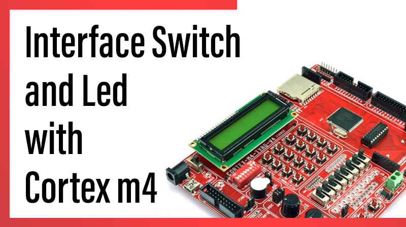
Interface Switch and Led with Cortex m4
This blog post explains how to interface switch and led with lpc4088 cortex m4 .
Steps to Blink led using switch with cortex m4 development board
- Power: In the PCONP register, set the PCGPIO bit
- Configure pins P4.0 to P4.15 as GPIO pins i.e. IOCON_P4_0 to IOCON_P4_15.
- Select LED pins P4.0 to P4.7 as output and SWITCH pins P4.8 to P4.15 as input
- Read the Switch status and Display its value in LED
C Source code to interface switch and led with cortex m4
#include "LPC407x_8x_177x_8x.h"

void delay_ms(long ms);

int main(void)
{
		//1. Set the PCGPIO bit
		LPC_SC->PCONP |= (1<<15);

		//2. Configure pins P4.0 to P4.15 as GPIO pins
		LPC_IOCON->P4_0 = 0;
		LPC_IOCON->P4_1 = 0;
		LPC_IOCON->P4_2 = 0;
		LPC_IOCON->P4_3 = 0;
		LPC_IOCON->P4_4 = 0;
		LPC_IOCON->P4_5 = 0;
		LPC_IOCON->P4_6 = 0;
		LPC_IOCON->P4_7 = 0;
		LPC_IOCON->P4_8 = 0;
		LPC_IOCON->P4_9 = 0;
		LPC_IOCON->P4_10 = 0;
		LPC_IOCON->P4_11 = 0;
		LPC_IOCON->P4_12 = 0;
		LPC_IOCON->P4_13 = 0;
		LPC_IOCON->P4_14 = 0;
		LPC_IOCON->P4_15 = 0;

		//3. Configure the pins P4.0 to P4.7 as output
		//   SWITCH pins P4.8 to P4.15 as input
		LPC_GPIO4->DIR= 0x00FF;

		while(1)
		{
			//4. Read the Switch Status and display it in LEDs
			LPC_GPIO4->PIN >>= 8;
			delay_ms(50);
		}
}

void delay_ms(long ms) 					// delay 1 ms per count @ CCLK 120 MHz
{
		long i,j;
		for (i = 0; i < ms; i++ )
		for (j = 0; j < 26659; j++ );
}