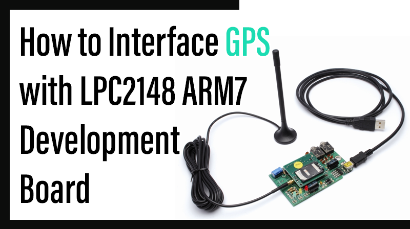
How to Interface GPS with LPC2148 ARM7 Development board
The ARM7 LPC2148 Development Board is specifically designed to help students to master the required skills in the area of embedded systems. The kit is designed in such way that all the possible features of the microcontroller will be easily used by the students. The kit supports in system programming (ISP) which is done through serial port.
NXP’s ARM7 (LPC2148), ARM Development Kit is proposed to smooth the progress of developing and debugging of various designs encompassing of High speed 32-bit Microcontrollers.
GPS (Global Positioning Systems)
The Global Positioning System (GPS) is a space-based satellite navigation system that provides location and time information in all weather, anywhere on or near the Earth, where there is an unobstructed line of sight to four or more GPS satellites.
Interfacing GPS
Fig. 1 shows how to interface the GPS with microcontroller. The GPS module continuously transmits serial data (RS232 protocol) in the form of sentences according to NMEA standards. The latitude and longitude values of the location are contained in the GPGGA sentence (refer NMEA format).To communicate over UART or USART, we just need three basic signals which are namely, RXD (receive), TXD (transmit), GND (common ground). So to interface UART with LPC2148, we just need the basic signals.

Interfacing GPS with LPC2148
Receive data from satellite to LPC2148 Development Board by using GPS module through UART0. The serial data is taken from the GPS module through MAX232 into the SBUF register of LPC2148 microcontroller (refer serial interfacing with LPC2148). The serial data from the GPS receiver is taken by using the Serial Interrupt of the controller. This data consists of a sequence of NMEA sentences from which GPGGA sentence is identified and processed.
Pin Assignment with LPC2148
Circuit Diagram to Interface GPS with LPC2148

Source Code
The first six bytes of the data received are compared with the pre-stored string and if matched then only data is further accounted for; otherwise the process is repeated again. From the comma delimited GPGGA sentence, latitude and longitude positions are extracted by finding the respective comma positions and extracting the data.
C Program to receives data from satellite to LPC2148
************************************************************************************
Title : Program to receive data from satellite to LPC2148 through UART0
************************************************************************************
#define CR 0x0D
#include
void init_serial (void);
int putchar (int ch);
int getchar (void);
unsigned char test;
int main(void)
{
char *Ptr = "*** UART0 Demo ***\n\n\rType Characters to be echoed!!\n\n\r";
VPBDIV = 0x02;
// Divide Pclk by two init_serial();
while(1)
{
while (*Ptr)
{
putchar(*Ptr++);
}
putchar(getchar());
// Echo terminal
}
}
void init_serial (void)
{
PINSEL0 = 0x00000005;
// Enable RxD0 and TxD0 U0LCR = 0x00000083;
//8 bits, no Parity, 1 Stop bit U0DLL = 0x000000C3;
//9600 Baud Rate @ 30MHz VPB Clock U0LCR = 0x00000003;
}
int putchar (int ch)
{
if (ch == '\n')
{
while (!(U0LSR & 0x20));
U0THR = CR;
}
while (!(U0LSR & 0x20));
return (U0THR = ch);
}
int getchar (void)
{
while (!(U0LSR & 0x01));
return (U0RBR);
}
To compile the above C code you need the KEIL software. They must be properly set up and a project with correct settings must be created in order to compile the code. To compile the above code, the C file must be added to the project.
In Keil, you want to develop or debug the project without any hardware setup. You must compile the code for generating HEX file. In debugging Mode, you want to check the port output without LPC2148 Development Board.
The Flash Magic software is used to download the hex file into your microcontroller IC LPC2148 through UART0.
Testing the GPS with LPC2148
Give +3.3V power supply to LPC2148 Development Board; connect +5V adapter with GPS module is connected with the LPC2148 Development Board. Open the Hyper Terminal screen, select which port you are using and set the default settings. Now the screen should show some text messages.
If you are not reading any data from UART0, then you just check the jumper connections & just check the serial cable is working. Otherwise you just check the code with debugging mode in Keil. If you want to see more details about debugging just see the videos in below link.
☞How to Create & Debug a Project in Keil.
General Information
☞For proper working use the components of exact values as shown in Circuit file. Wherever possible use new components.
☞Solder everything in a clean way. A major problem arises due to improper soldering, solder jumps and loose joints.
☞Use the exact value crystal shown in schematic.
☞More instructions are available in following articles,
How to Interface UART with LPC2148 ARM7 Development Board