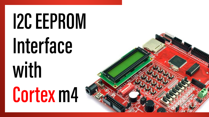
I2C EEPROM Interface with Cortex m4
This example describes how to make a communication with I2C EEPROM
Procedure for EEPROM interface with Cortex M4
- Initialize UART0
- Power: In the PCONP register, set the PCI2C0 bit
- Configure pins P0.27 (CH0) and P0.28 for I2C function using IOCON registers
- Clear all the I2C registers and Flags
- Enable I2C
- Configure the I2C frequency as 100KHz or 400KHz
- Enable I2C Interrupt
Write a block data: - Send START
- Send device address with write
- Send the block address where we going to write a block of data
- Send a block of data
- Send STOP signal
Read a block of data: - Send START
- Send device address with write
- Send the block address where we are going to read a block of data
- Send a REPEATED START
- Send device address with read
- Read a byte of data and send ACK signal
- Send a NACK signal if the byte read is the last byte
- Send STOP
- Display the data received in HyperTerminal
#include <LPC407x_8x_177x_8x.h>
#include "uart0.h"

#define DEVICE_ADDR 0xA0

unsigned char Status=0,rbuf[20],tbuf[20]="ARM CORTEX M4\r",Str[6];
unsigned char Status_Flag=0,i=0;

void Init_I2C0(void);
void Page_Write(unsigned char *str);
void Page_Read(unsigned char *str);
void wait_i2c(void);
void delay_ms(long ms);
void Start(void);
void Wait_I2C(void);

void I2C0_IRQHandler(void)
{
		Status_Flag = 1;
		Status = LPC_I2C0->STAT;									//	Read Status byte
		LPC_I2C0->CONCLR =	0x28;									//  Clear Interrupt Flag
}

int main(void)
{
		//1.Initialize UART
		init_serial();
		Init_I2C0();
		delay_ms(100);

		Page_Write(tbuf);
		delay_ms(100);

		while(1)
		{
			Page_Read(rbuf);
			//21. Display the read data in HyperTerminal
			UART0_puts(rbuf);
			delay_ms(1000);
		}
}

void Init_I2C0(void)
{
	//2. set bit PCI2C0
		LPC_SC->PCONP |= (1 << 7); 										/* enable power to UART0*/

	//3. Configure pins P0.27 and P0.28 for I2C Clock and data
		LPC_IOCON->P0_27 |=  1;        								/* Pin P0.2 used as I2C DATA */
		LPC_IOCON->P0_28 |=  1;        								/* Pin P0.3 used as I2C CLK */

	//4. Clear all the Registers
		LPC_I2C0->CONCLR=	0x6C;

	//5. Enable I2C
		LPC_I2C0->CONSET=	0x40;

	//6. Set I2C Frequency as 400KHz
	//   30MHz/400KHz = 75=SCLH+SCLL=38+37=75
		LPC_I2C0->SCLH  = 38;
		LPC_I2C0->SCLL  = 37;

	//7. Enable Interrupt
		NVIC->ISER[0] |= (1<<10);					//Enable I2C0
		NVIC->IP[2]   |= (0x3<<19); 			//Interrupt Priority 0-High, 31-low
}

void Start(void)
{
	 LPC_I2C0->CONCLR = 0x2C;
	 LPC_I2C0->CONSET = 0x20;
	 Wait_I2C();
}

void Page_Write(unsigned char *str)
{

	 Start();																				//8. Send Start

	 LPC_I2C0->DAT = 0xA0;													//9. Send device Address + write
	 Wait_I2C();

	 LPC_I2C0->DAT=0;																//10. Send block address High
	 Wait_I2C();

	 LPC_I2C0->DAT=0;																//10. Send block address Low
	 Wait_I2C();

	 for(i=0;i<16;i++)
	 {
			LPC_I2C0->DAT = str[i];											//11. Send a block of data
		  Wait_I2C();
	 }
	 LPC_I2C0->CONSET = 0x10; 											//12. Send STOP
}

void Page_Read(unsigned char *str)
{
	 Start();																				//13. Send Start

	 LPC_I2C0->DAT    = 0xA0;												//14. Send device Address + write
	 Wait_I2C();

	 LPC_I2C0->DAT=0;																//15. Send block address High
	 Wait_I2C();

	 LPC_I2C0->DAT=0;
	 Wait_I2C();																		//15. Send block address Low

	 Start();	 																			//16. Send r-Start

 	 LPC_I2C0->DAT = 0xA1;													//17. Send device Address + read
	 Wait_I2C();

	 for(i=0;i<15;i++)													  	//18.	Read a byte of data and send ACK signal
	 {
			LPC_I2C0->CONSET = 0x04;
			Wait_I2C();
			str[i] = LPC_I2C0->DAT;
	 }

	 //Last byte																		//19.	Send a NACK signal and Read the Last byte
	 LPC_I2C0->CONCLR = 0x4;
	 Wait_I2C();
	 str[i] = LPC_I2C0->DAT;
	 LPC_I2C0->CONSET=0x10; 												//20. Send STOP
}

void Wait_I2C(void)
{
		while(Status_Flag == 0);
		Status_Flag = 0;
}

void delay_ms(long ms) 					// delay 1 ms per count @ CCLK 120 MHz
{
		long i,j;
		for (i = 0; i < ms; i++ )
		for (j = 0; j < 26659; j++ );
}