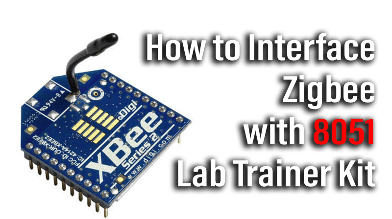
How to Interface Zigbee with 8051 Lab Trainer Kit
This blog post summarize how to interface zigbee with 8051 using assembly programming
PS-TRAINER-8051 trainer kit is proposed to smooth the progress of learning and developing designs of MCU from Intel and NXP. It has the facility to connect PC’s 101/104 Keyboard, to enter user programs in Assembly languages. Serial communication achieved using 8051. It also supports C & assembly language in standalone kit (P89V51RD2). It’s designed as to facilitate On-board Programmer for NXP 8051 MCU through ISP on serial port.
ZIGBEE
ZigBee is a specification for a suite of high level communication protocols using small, low-power digital radios based on an IEEE 802 standard for personal area networks.
DIGI ZIGBEE
The Digi Xbee 802.15.4 modules are the easiest to use, most reliable and cost-effective RF devices we’ve experienced. The 802.15.4 Xbee modules provide two friendly modes of communication – a simple serial method of transmit/receive or a framed mode providing advanced features. These modules can communicate point to point, from one point to a PC, or in a mesh network.
Interfacing Zigbee with 8051
Fig. 1 shows how to interface the Zigbee with microcontroller. The Xbee modules work at the 2.4 GHz frequency which means smaller board and antenna size. Xbee modules have the ability to transmit Digital, PWM, Analog or Serial RS232 signals wirelessly. To communicate over UART or USART, we just need three basic signals which are namely, RXD (receive), TXD (transmit), GND (common ground). So to interface UART with 8051, we just need the basic signals.
Interface Zigbee with 8051
We now want to interface the ZigBee module with 8051 trainer Board for wireless controlling application through UART0. The data communication is done in RF communication by using the ZigBee module through MAX232 into the SBUF register of 8051 microcontroller (refer serial interfacing with 8051). The serial data from the Zigbee receiver is taken by using the Serial Interrupt of the controller. +5V and ground is connected to provide power to the module. While TX and RX pin is connected for communication.
PIN ASSIGNMENT WITH 8051
Circuit diagram to interface Zigbee with 8051
Assembly program to interface Zigbee with 8051
| MEMORY ADDRESS | OPCODE | MNEMONICS |
| 8500 | 75,89,21 | MOV TMOD,#21 |
| 8503 | 75 8D FD | MOV TH1,#FD |
| 8506 | 75 98 52 | MOV SCON,#52 |
| 8509 | D2 8E | SETB TR1 |
| 850B | 74 41 | H:MOV A,#41 |
| 850D | B1 11 | ACALL TXMT |
| 850F | 80 FA | SJMP H |
| 8511 | 30 99 FD | TXMT:JNB TI,TXMT |
| 8514 | C2 99 | CLR TI |
| 8516 | F5 99 | MOV SBUF,A |
| 8518 | 22 | RET |