

How to Interface with UART Camera using C6745 and MATLAB
Call for Price
The TMS320C6745 EVALUATION BOARD is specially designed for developers in dsp field as well as beginners. The kit is designed in such way that all the possible features of the DSP will be easily used by everyone.
Description
TMS320C6745 Evaluation Board
The TMS320C6745 Evaluation Board is specially designed for developers in dsp field as well as beginners. The kit is designed in such way that all the possible features of the DSP will be easily used by everyone.
The kit supports in Code Composer Studio3.3 and later, with XDS100 v1 USB Emulator which is done USB port.
Camera
About UART CAMERA please refer the link
How to Interface SPI TFT with TMS320C6745 DSP using SPI protocol method
In the above link complete UART Camera solutions was provided for your reference. In this tutorial here we study about the C328-7640 UART camera interface with TMS320C6745 DSP kit and MATLAB GUI.
Note: Datasheets, ucamdemo software and all supported matlab files will get while downloading the source code of this project.
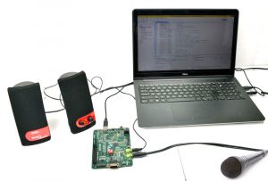
TMS320C6745 Used pins and Methods
On board TMS320C6745 UART, D1 Led and Dip Switches are used in this project. From the 8 pin Dip switch only one switch is going to control the capturing the image from camera and transferring image to MATLAB GUI.
In TMS320C6745 DSP kit, only one uart is available but we need to connect the two things at the same time so we need some input signal to hold the execution once it captured and then to stop transferring the image to MATLAB GUI.
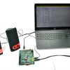
RS232 Cable Used:
☞Cross serial cable [TMS320C6745 kit and Uart camera].
☞Straight serial cable [TMS320C6745 kit and PC].
Steps to follow:
☞First connect straight cable between PC and Uart Camera.
☞Power the uart camera module.
☞Open the ucamdemo software.
☞Choose the appropriate com port and select 115200 baud rate, click open comms, send the SYNC byte., if you successfully received with response and acknowledge bytes (Don’t reset the camera or don’t do the power reset also)
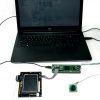
☞Remove the straight cable between PC and Uart Camera.
☞Fix the cross cable between TMS320C675 kit and Uart camera.
☞Make sure GP0_0 pin in switch state is high.
☞Compile, Debug and Run the c code.
☞Wait for the change state signal high (D1 Led will glow).
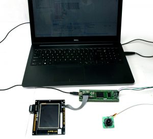
☞Remove the cross cable between TMS320C675 kit and Uart camera.
☞Fix the straight cable between TMS320C675 kit and Uart camera.
☞Open the Matlab and run the cmoscam.m file.
☞Matlab GUI will open and click the receive button.
☞Change the GP0_0 switch state to low.
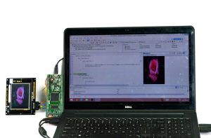
☞Now the TMS320C6745 kit transfers the pixel values to MATLAB GUI through the UART.
Note: This Uart Camera work with 115200 baud rate.
How to Interface with UART Camera Output Image


C Program to capture an image from UART camera and display in MATLAB GUI
Title : Program to capture an image from UART camera and display an image in MATLAB GUI using TMS320C6745 kit
#include "stdio.h"
#include "c6745.h"
#include "c6745_uart.h"

#define CHANGE 0x00010000
#define FINISH 0x00020000

void Uart_Tx(unsigned char tx);
Uint8 Uart_Rx();
void SYNC_Command();

UART_Handle uart0;

char receive;

unsigned char SYNC[7] = {0xAA,0x0D,0x00,0x00,0x00,0x00};
unsigned char  ACK[7] = {0xAA,0x0E,0x0D,0xFF,0x00,0x00};
unsigned char  INIT[7]= {0xAA,0x01,0x00,0x06,0x05,0x03};
unsigned char  SNAP[7]= {0xAA,0x05,0x01,0x00,0x00,0x00};
unsigned char GPIC[7]= {0xAA,0x04,0x01,0x00,0x00,0x00};
unsigned char GPACK[7] = {0xAA,0x0E,0xFF,0x00,0x00,0x00};
unsigned char SYNC_RESP[13];
unsigned char INIT_RESP[13];
unsigned char SNAP_RESP[13];
unsigned char GPIC_RESP[13];
unsigned char PIXEL[38400];	//153600
unsigned char check[2];

unsigned int i,k,rec=0;
void Gets(unsigned char *string, unsigned int n);
void uart_puts(unsigned char *string,unsigned int n);
void ImgtoMatlab();
void  DelayMs(Uint32 Ms);

Uint32 *gpio_in_data01,*gpio_out_data01,*gpio_dir01;
Uint32 Value;

void main()
{
	gpio_in_data01 = (Uint32 *)0x01E26020;
	gpio_dir01 = (Uint32 *)0x01E26010;
	gpio_out_data01 = (Uint32 *)0x01E26014;

	*gpio_dir01 = 0xF000FFFF;

    C6745_init( );
    uart0 = C6745_UART_open( 1, 115200 );
    *gpio_out_data01 &= ~FINISH;
    *gpio_out_data01 &= ~CHANGE;
	rec=0;
    for(k=0;k<13;k++)
    {
		SYNC_RESP[k]=INIT_RESP[k]=SNAP_RESP[k]=GPIC_RESP[k]=0xFF;
    }

    for(k=0;k<38400;k++)
    {
    	PIXEL[k]=0xFF;
    }
    SYNC_Command();
    *gpio_out_data01 |= CHANGE;

    while(1)
    {
    	Value = *gpio_in_data01;
    	Value &= 0x00000001;
    	if(Value==0x0000000)
    	{
    		*gpio_out_data01 &= ~CHANGE;
    		ImgtoMatlab();
    	}
    }
}

void Uart_Tx(unsigned char tx)
{
	while(((uart0->regs->LSR)&0x60)==0);
	uart0->regs->THR = tx;
}

Uint8 Uart_Rx()
{
	rec++;
	while(((uart0->regs->LSR) & 0x1)==0);
	receive = uart0->regs->THR;
	return receive;
}

void SYNC_Command()
{
	uart_puts(SYNC,6);
	Gets(SYNC_RESP,12);
	uart_puts(ACK,6);

	uart_puts(INIT,6);
	Gets(INIT_RESP,6);

	uart_puts(SNAP,6);
	Gets(SNAP_RESP,6);

	uart_puts(GPIC,6);
	Gets(GPIC_RESP,12);
	Gets(PIXEL,38400);
	uart_puts(GPACK,6);

}


void Gets(unsigned char *string, unsigned int n)
{
	unsigned int i=0,J=0;
	do
	{
		*(string+i)= Uart_Rx();
		 J = *(string+i);  //Transmit_0(J);
		i++;
	}
	while(i<n);
//	while((J<='\n') && (J!='\r') && (J!=EOF));

	i++;
	*(string+i) = NULL;
}

void uart_puts(unsigned char *string,unsigned int n)
{
   while(n>0){
   	Uart_Tx(*string++);
   	n--;
   }
}

void ImgtoMatlab()
{
	for(k=0;k<38400;k++)
    {
    	Uart_Tx(PIXEL[k]);
    }
	DelayMs(100);
	*gpio_out_data01 |= FINISH;
	DelayMs(100);
	while(1);
//	main();
}

void DelayMs(Uint32 Ms)
{
	Uint32 i;
	while(Ms>0)
	{
		for(i=0;i<30000;i++);
		Ms--;
	}
}
Additional information
| Weight | 1.000000 kg |
|---|
Reviews
There are no reviews yet.