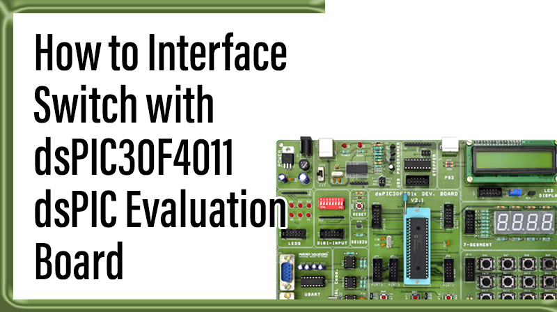
How to Interface Switch with dsPIC30F4011 dsPIC Evaluation Board
The DsPIC30F4011 Evaluation Board is specifically designed to help students to master the required skills in the area of embedded systems. The kit is designed in such way that all the possible features of the microcontroller will be easily used by the students. The kit supports in system programming (ISP) which is done through USB port.
Microchip’s dsPIC30F (dsPIC30F4011), Evaluation Kit is proposed to smooth the progress of developing and debugging of various designs encompassing of High speed 16-bit Microcontrollers.
Switch
A switch is an electrical component that can break an electrical circuit, interrupting the current or diverting it from one conductor to another. A switch may be directly manipulated by a human as a control signal to a system, or to control power flow in a circuit.
Interfacing Switch
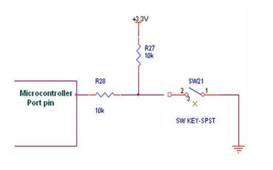
Fig. 1 shows how to interface the switch to microcontroller. A simple switch has an open state and closed state. However, a microcontroller needs to see a definite high or low voltage level at a digital input. A switch requires a pull-up or pull-down resistor to produce a definite high or low voltage when it is open or closed. A resistor placed between a digital input and the supply voltage is called a “pull-up” resistor because it normally pulls the pin’s voltage up to the supply.
Interfacing Switch with dsPIC30F4011
We now want to control the LED by using switches in DsPIC30F4011 Evaluation Board. It works by turning ON a LED & then turning it OFF when switch is going to LOW or HIGH.
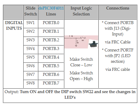
The DsPIC30F4011 Evaluation Board has eight numbers of point LEDs, connected with I/O Port lines (PORTB.0 – PORTB.3) to make port pins high. Eight switches, connected with I/O port lines (PORTB.4 – PORTB.7) are used to control eight LEDs.
Pin Assignment with dsPIC30F4011
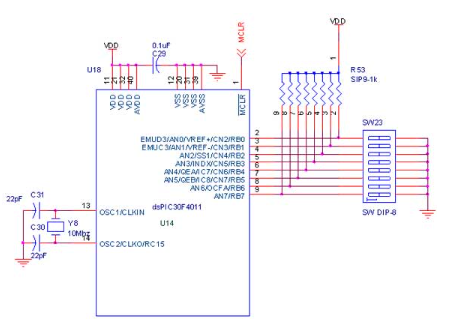
Circuit Diagram to Interface Switch with dsPIC30F4011
Source Code
The Interfacing switch with dsPIC30F4011 program is very simple and straight forward, that controls led by using switches when it going LOW or HIGH.
C Program to switch functions using dsPIC30F4011
Title : Program to Blink LEDs controlling by switches
#include "p30f4011.h"
#include "delay.c"
_FOSC(CSW_FSCM_OFF & XT);
// Set up Crystal without PLL _FWDT(WDT_OFF);
// Turn off the Watch-Dog Timer _FBORPOR(PWRT_OFF & MCLR_EN);
//Enable MCLR& off power-up timers _FGS(CODE_PROT_OFF);
int main()
{
Delay_ms10M(10);
ADPCFG = 0xffff;
CNPU1 = 0xffff;
Delay_ms10M(10);
TRISB = 0xffff;
LATB = 0xffff;
LATF = 0x0000;
TRISF = 0x0000;
while(1)
{
LATF = PORTB; Delay_ms10M(1000);
}
}
To compile the above C code you need the MPLAB software.
They must be properly set up and a project with correct settings must be created in order to compile the code. To compile the above code, the C file must be added to the project.
In Mplab, you want to develop or debug the project without any hardware setup. You must compile the code for generating HEX file. In debugging Mode, you want to check the port output without DsPIC30F4011 Evaluation Board.
The PICKIT2 software is used to download the hex file into your microcontroller IC DSPIC30F4011 through USB.
Testing the switch with DSPIC30F4011
Give +12V power supply to DsPIC30F4011 Evaluation Board; the switches are connected with the DsPIC30F4011 Evaluation Board. After that ,Check the LED’s & switches are working or not. If you not reading any output signal in LED, then you just check the jumper connections. Otherwise you just check the code with debugging mode in Mplab.
If you want to see more details about debugging just see the videos in below link.
☞How to Create & Debug a Project in Mplab using dsPIC30F.
General Information
☞For proper working use the components of exact values as shown in Circuit file. Wherever possible use new components.
☞Solder everything in a clean way. A major problem arises due to improper soldering, solder jumps and loose joints.
☞Use the exact value crystal shown in schematic.
☞More instructions are available in following articles,
dSPIC Evaluation Board
User Manual for DSPIC30F4011 Evaluation Kit