

How to Interface SPI TFT &UART CAMERA with TMS320C6745 DSP
Call for Price
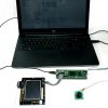
The TMS320C6745 EVALUATION BOARD is specially designed for developers in dsp field as well as beginners. The kit is designed in such way that all the possible features of the DSP will be easily used by everyone.
Description
The TMS320C6745 EVALUATION BOARD is specially designed for developers in dsp field as well as beginners. The kit is designed in such way that all the possible features of the DSP will be easily used by everyone.
The kit supports in Code Composer Studio3.3 and later, with XDS100 v1 USB Emulator which is done USB port.
TFT
About SPI TFT please refer the link
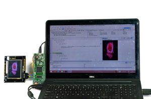
How to Interface SPI TFT with TMS320C6745 DSP using SPI protocol method
In the above link complete TFT solutions was provided for your reference. In this tutorial here we study about the C328-7640 UART camera interface and implement with SPI TFT using TMS320C6745 DSP kit.
SPI C Code
void GLCD_SPI_Read_Write(unsigned char DataByte)
{
     SPI_SPIDAT1 = DataByte;
     while((SPI_SPIBUF & 0x20000000)==1);
}

/* Write Address Command(Index Reg.)(Use Device ID=0) */
void GLCD_Write_Command(unsigned int GLCD_Command)
{
     GLCD_CS_LOW();      // Enable GLCD Interface
     GLCD_SPI_Read_Write(0x70);       // Sent Byte 1 = [Device ID Code:01110[0]]+[RS:0] + [R/W:0]
     GLCD_SPI_Read_Write(0x00);       // Sent Byte 2 = data 8 bit High Index Reg.: 0x00
    GLCD_SPI_Read_Write(GLCD_Command);      // Sent Byte 3 = data 8 bit Low index reg. : cmm
    GLCD_CS_HIGH();
    // Disable GLCD Interface
}
/* Write data to LCD (Use Device ID=0) */
void GLCD_Write_Data(unsigned int GLCD_Data)
{
     GLCD_CS_LOW();        // Enable GLCD Interface
     GLCD_SPI_Read_Write(0x72);        // Byte 1 = [Device ID Code:01110[0]]+[RS:1] + [R/W:0]
     GLCD_SPI_Read_Write(GLCD_Data >> 8);   // Byte 2 = Data 8 bit High
    GLCD_SPI_Read_Write(GLCD_Data);     // Byte 3 = Data 8 bit Low

    GLCD_CS_HIGH();
    // Disable GLCD Interface
}
C328-7640 module
The C328 module is a highly integrated serial camera board that can be attached to a wireless or PDA host performing as a video camera or a JPEG compressed still camera. It provides a serial interface (RS-232) and JPEG compression engine to act as a low cost and low powered camera module for high-resolution serial bus security system or PDA accessory applications.
Camera Sensor
The C328-7640 module uses OmniVision OV7640/8 VGA color digital Camera Chips with an 8-bit YCbCr interface.
OV528 Serial Bridge
The OV528 Serial Bridge is a JPEG CODEC embedded controller chip that can compress and transfer image data from CameraChips to external device. The OV528 takes 8-bit YCbCr 422 progressive video data from an OV7640/8 CameraChip.
The camera interface synchronizes with input video data and performs down sampling, clamping and windowing functions with desired resolution, as well as color conversion that is requested by the user through serial bus host commands.
The JPEG CODEC can achieve higher compression ratio and better image quality for various image resolutions.
Program EEPROM
A serial type program memory is built-in for C328-7640 to provide a set of user-friendly command interfacing to external host.
Serial Interface Timing Diagram
Single Byte Timing Diagram
A single byte RS-232 transmission consists of the start bit, 8-bit contents and the stop bit. A start bit is always 0, while a stop bit is always 1. LSB is sent out first and is right after the start bit.
![]()
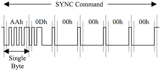
Command Timing Diagram
A single command consists of 6 continuous single byte RS-232 transmissions. The following is an example of SYNC (AA0D00000000h) command.
Command Set
The C328-7640 module supports total 11 commands for interfacing to host as following:
|
Command |
ID Number |
Parameter 1 |
Parameter 2 |
Parameter 3 |
Parameter 4 |
|
Initial |
AA01h |
00h |
Color type |
RAW Resolution (Still image only) |
JPEG Resolutions |
|
Get Picture |
AA04h |
Picture Type |
00h |
00h |
00h |
|
Snapshot |
AA05h |
Snapshot Type |
Skip Frame Low Byte |
Skip Frame High Byte |
00h |
|
Set Package Size |
AA06h |
08h |
Package size Low Byte |
Package Size High Byte |
00h |
|
Set Baudrate |
AA07h |
1st Divider |
2nd Divider |
00h |
00h |
|
Reset |
AA08h |
Reset Type |
00h |
00h |
Xxh* |
|
Power off |
AA09h |
00h |
00h |
00h |
00h |
|
Data |
AA0Ah |
Data type |
Length Byte 0 |
Length Byte 1 |
Length Byte 2 |
|
SYNC |
AA0Dh |
00h |
00h |
00h |
00h |
|
ACK |
AA0Eh |
Command ID |
ACK counter |
00h/Package ID Byte 0 |
00h / Package ID Byte 1 |
|
NAK |
AA0Fh |
00h |
NAK counter |
Error Number |
Ooh |
|
Light Frequency |
AA13h |
Frequency Type |
00h |
00h |
00h |
*If the parameter is 0xFF,the command is a special Reset command and the firmware Responds to it immediately.
For more details about command set kindly download the camera datasheet along with the source code.
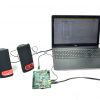
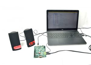
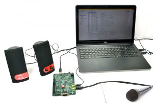
How to Interface SPI TFT &UART CAMERA Output Image


C Program to capture an image from UART camera and display an image in TFT
Title : Program to capture an image from UART camera and display an image in SPI TFT using TMS320C6745 kit
#include "stdio.h"
#include "c6745.h"
#include "../Header/c6745.h"
#include "../Header/c6745_led.h"
#include "../Header/c6745_gpio.h"
#include "spitft.h"
#include "TFT.h"
#include "Font.h"
#include "c6745_uart.h"

void Uart_Tx(unsigned char tx);
Uint8 Uart_Rx();
void SYNC_Command();
void Gets(unsigned char *string, unsigned int n);
void uart_puts(unsigned char *string,unsigned int n);
void PixeltoImage();
void Poweroff();

UART_Handle uart0;

char receive;

unsigned char SYNC[7] = {0xAA,0x0D,0x00,0x00,0x00,0x00};
unsigned char  ACK[7] = {0xAA,0x0E,0x0D,0xFF,0x00,0x00};
unsigned char  INIT[7]= {0xAA,0x01,0x00,0x06,0x03,0x05};
unsigned char  SNAP[7]= {0xAA,0x05,0x01,0x00,0x00,0x00};
unsigned char  GPIC[7]= {0xAA,0x04,0x01,0x00,0x00,0x00};
unsigned char GPACK[7] = {0xAA,0x0E,0xFF,0x00,0x00,0x00};
unsigned char POWOFF[7] = {0xAA,0x09,0x00,0x00,0x00,0x00};
unsigned char SYNC_RESP[13];
unsigned char INIT_RESP[13];
unsigned char SNAP_RESP[13];
unsigned char GPIC_RESP[13];
unsigned char PIXEL[153600];
unsigned char check[2];
unsigned int i,k;
unsigned int inc=0;
unsigned int  *image;

int main(void)
{
  // Start Initialize GLCD
  image = (unsigned int *)0xc0000000;
  C6745_init( );
          delay_ms(100);
          Initial_Hardware();
          GLCD_Init();
          delay_ms(100);
          uart0 = C6745_UART_open( 1, 115200 );
    for(k=0;k<13;k++)
    {
    SYNC_RESP[k]=INIT_RESP[k]=SNAP_RESP[k]=GPIC_RESP[k]=0xFF;
    }

    for(i=0;i<76800;i++)
          *(image+i)=0;

  SYNC_Command();

          PixeltoImage();

    plot_picture_hor(image,0,0,320,240);

    while(1);
}

void Uart_Tx(unsigned char tx)
{
  while(((uart0->regs->LSR)&0x60)==0);
  uart0->regs->THR = tx;
}

Uint8 Uart_Rx()
{
  inc++;
  while(((uart0->regs->LSR) & 0x1)==0);
  receive = uart0->regs->THR;
  return receive;
}

void SYNC_Command()
{
  uart_puts(SYNC,6);
  Gets(SYNC_RESP,12);
  uart_puts(ACK,6);

  uart_puts(INIT,6);
  Gets(INIT_RESP,6);

  uart_puts(SNAP,6);
  Gets(SNAP_RESP,6);

  uart_puts(GPIC,6);
  Gets(GPIC_RESP,12);
  Gets(PIXEL,153600);
  uart_puts(GPACK,6);

}

void Gets(unsigned char *string, unsigned int n)
{
  unsigned int i=0,J=0;
  do
  {
          *(string+i)= Uart_Rx();
           J = *(string+i);  //Transmit_0(J);
          i++;
  }
  while(i<n);

  i++;
  *(string+i) = NULL;
}

void uart_puts(unsigned char *string,unsigned int n)
{
   while(n>0){
          Uart_Tx(*string++);
          n--;
   }
}

void PixeltoImage()
{
  unsigned int a,c,addr;
  unsigned short msb=0,lsb=0,data=0;

  a=0;
  addr=0;
  for(c=0;c<65000;c++)
  {
          msb = PIXEL[a];
          a++;
          lsb = PIXEL[a];
          a++;

          data = msb<<8;
          data |= lsb;
          *(image+addr) = data;
          addr+=2;
  }
}

void Poweroff()
{
  uart_puts(POWOFF,6);
}
Additional information
| Weight | 1.000000 kg |
|---|
Reviews
There are no reviews yet.