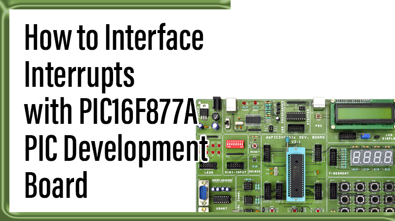
How to Interface Interrupts with PIC16F877A – PIC Development Board
The PIC16F/18F Development Board is specifically designed to help students to master the required skills in the area of embedded systems. The kit is designed in such way that all the possible features of the microcontroller will be easily used by the students. The kit supports in system programming (ISP) which is done through USB port.
Microchip’s PIC (PIC16F877A ), PIC16F/18F Development Kit is proposed to smooth the progress of developing and debugging of various designs encompassing of High speed 8-bit Microcontrollers.
External Interrupts
An interrupt caused by an external source such as the computer operator, external sensor or monitoring device, or another computer. Interrupts are special events that require immediate attention.
Interfacing External Interrupts
Fig. 1 shows how to interface the External Interrupt to microcontroller. Interrupts cause the processor to cease the running task to serve a special task for which the interrupt event had occurred. After the special task is over, the processor resumes performing the original task.
The processor can also serve these events by polling method. But polling is an inefficient technique as compared to interrupts. In the polling method, the processor has to continuously wait for the event signal. Thus it always remains busy using extra resources.
Interfacing External Interrupts with PIC16F877A
We now want to display some messages in PC when occur an external interrupt signal in PIC16F/18F Development Board. The Interrupt signal is occurred by using switches. When the switch is pressed to LOW, then the external interrupt is occurred.
The Vectored Interrupt Controller (VIC) takes 32 interrupt request inputs and programmable assigns them into 3 categories, FIQ, vectored IRQ, and non-vectored IRQ.
The PIC16F/18F Development Board has only one External Interrupt, connected with I/O Port line (PORTB.0) as a switch.
Pin Assignment with PIC16F877A
Circuit Diagram for Ext-Interrupt with PIC16F877A
Source Code
The Interfacing External Interrupt with PIC16F877A program is very simple and straight forward, that accessed by using switches. When the two external interrupts occurring, some messages are displayed in PC through serial port at 9600 baud rate. The C programs are written in Mplab software & Hi-Tech Compiler.
C Program to interface Ext-Interrupt using PIC16F
#include
// Define PIC Registers __CONFIG(0x3f72);
//Select HS oscillator, Enable (PWRTE,BOREN),
//Disable (CPD,CP,WDTEN,In-circuit Debugger)
void DelayMs(unsigned int);
void main()
{
OPTION_REG=0;
// Enable Internal Pull-ups and Interrupt on falling edge TRISB=0x01;
// Configure RB0 as I/P TRISC=0x00;
// Configure PORTC as O/P PORTC=0;
PORTB=0; INTCON=0x90;
// Enable the Global Interrupt & External Interrupt while(1);
}
void interrupt rb0_int(void)
{
if(INTF)
// Wait until External Interrupt occurs
{
RC0^=1;
// Toggle PORTC Pin RC0 INTF=0;
// clear the External Interrupt flag while((PORTB & 0x01)==0);
// stay until interrupt on pin RB0 released
}
}
void DelayMs(unsigned int Ms)
{
int delay_cnst;
while(Ms>0)
{
Ms--;
for(delay_cnst = 0;delay_cnst <220;delay_cnst++);
}
}
To compile the above C code you need the Mplab software & Hi-Tech Compiler. They must be properly set up and a project with correct settings must be created in order to compile the code. To compile the above code, the C file must be added to the project.
In Mplab, you want to develop or debug the project without any hardware setup. You must compile the code for generating HEX file. In debugging Mode, you want to check the port output without PIC16F/18F Development Board
The PICKIT2 software is used to download the hex file into your microcontroller IC through USB port.
Testing the External Interrupts with PIC16F877A
Give +12V power supply to PIC16F/18F Development Board; the serial cable is connected between the PIC16F/18F Development Board and PC. Open the Hyper Terminal screen, select which port you are using and set the default settings. Now the screen should show which external interrupt is selected.
When you pressed the external interrupt key, the screen should update which interrupt is now pressed. The Interrupts are controlled by using switches. If any data is not coming in Hyper Terminal, then you just check the serial cable is working or not. Otherwise you just check the code with debugging mode in Mplab. If you want to see more details about debugging just see the videos in below link.
☞PIC16F using Hi-Tech Compiler.” PIC16F using Hi-Tech Compiler.
General Information
☞For proper working use the components of exact values as shown in Circuit file. Wherever possible use new components.
☞Solder everything in a clean way. A major problem arises due to improper soldering, solder jumps and loose joints.
☞Use the exact value crystal shown in schematic.