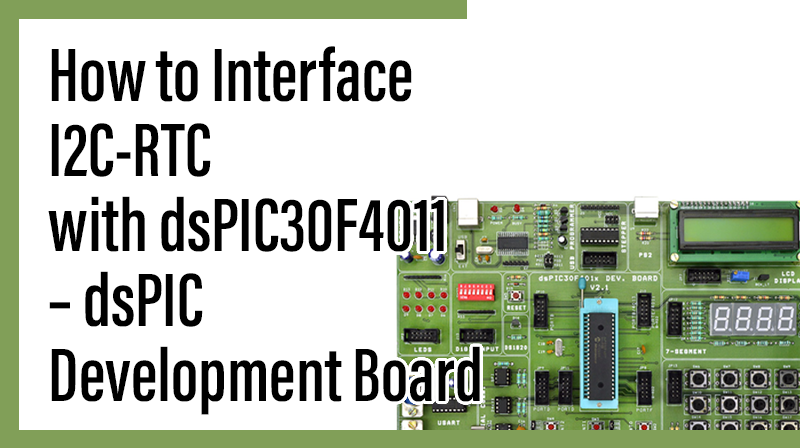
How to Interface I2C-RTC with dsPIC30F4011 – dsPIC Development Board
The DsPIC30F4011 Development Board is specifically designed to help students to master the required skills in the area of embedded systems. The kit is designed in such way that all the possible features of the microcontroller will be easily used by the students. The kit supports in system programming (ISP) which is done through USB port.
Microchip’s dsPIC30F (dsPIC30F4011), Development Kit is proposed to smooth the progress of developing and debugging of various designs encompassing of High speed 16-bit Microcontrollers. In this post , we can see how to interface I2C-RTC with DsPIC30F4011 Development Board.
I2C (Inter Integrated Circuit)
The I2C (Inter-IC) bus is a bi-directional two-wire serial bus that provides a communication link between integrated circuits (ICs).I2C is a synchronous protocol that allows a master device to initiate communication with a slave device. Data is exchanged between these devices.
RTC (Real Time Clock)
Real Time Clock is a computer clock which tracks the current time. It can be used in computer systems, servers etc . Mostly it can be used in electronic devices and embedded systems.
Interfacing I2C – RTC
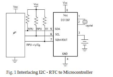
Fig. 1 shows how to interface the EEPROM with microcontroller through I2C. I2C is a Master-Slave protocol. I2C has a clock pulse along with the data. The master device controls the clock line, SCL. This line dictates the timing of all transfers on the I2C bus. No data will be transferred unless the clock is manipulated.
I2c bus supports many devices, each device is recognized by a unique address—whether it’s a micro-controller, LCD Driver, memory or keyboard interface and can operate as transmitter or receiver based on the functioning of the device. The controller designed controls the RTC ds1307 device through I2C protocol. The I2C Controller here acts as a master device and controls RTC ds1307 which acts as a slave. The read operation is accomplished by sending a set of control signals including the address and/or data bits. The control signals must be accompanied with proper clock signals.
Interface I2C – RTC with dsPIC30F4011
We now want to read date & time by using I2C – RTC in DsPIC30F4011 Development Board. Wiring up an I2C based RTC to the I2C port is relatively simple. The RTC also makes the software easier as it takes care of all calendar functions; accounting for leap years etc. The DS1307 (RTC) Real Time Clock IC (an I2C real time clock) is an 8 pin device using an I2C interface.
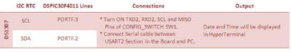
In dsPIC30F4011 Development Kit, 2 nos. of RTC lines are controlled by I2C Enabled drivers. I2C Lines serial clock SCL (PORTF.3), serial data SDA (PORTF.2) connected to the I2C based serial RTC ds1307 IC. The date & times are read in dsPIC30F4011 Development Kit by using these SDA & SCL I2C lines.
Pin Assignment for interface I2C- RTC with dsPIC30F4011
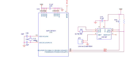
Circuit Diagram for Interface I2C–RTC with dsPIC30F4011
Source Code
The Interfacing I2C – RTC with dsPIC30F4011 program is very simple and straight forward that read date & time in RTC by using I2C & the value is displayed in serial port. A delay is occurring in every single data read from RTC. The delay depends on compiler how it optimizes the loops as soon as you make changes in the options the delay changes.
C Program to interface I2C – RTC with dsPIC30F4011
Title : Program to read date & time of I2C – RTC
#include "p30f4011.h"
_FOSC(CSW_FSCM_OFF & XT);
_FWDT(WDT_OFF);
_FBORPOR(PBOR_ON & MCLR_EN);
_FGS(CODE_PROT_OFF);
#define XTFREQ 10000000     / /10Mhz crystal
#define I2C_FREQ 400000
#define FOSC XTFREQ/4
#define BAUDRATE 9600
#define BRGVAL ((FOSC/BAUDRATE)/16)-1
#define I2C_Baud (((XTFREQ/I2C_FREQ)-(XTFREQ/1111111))-1)
#define I2C_WRITE 0xd0
#define I2C_READ 0xd1 unsigned char sec,min,hour,day,date,month,year, i,temp,String[3],Dt_Tm_Arr[20];
unsigned char data_ar[7]={0x45,0x59,0x71,0x04,0x07,0x10,0x08};
void Serial_init(void);
void I2C_Write(unsigned char);
void DS1307Write(unsigned char,unsigned char);
unsigned char DS1307Read(unsigned char);
void DelayMs(unsigned int);
void Puts(unsigned char *);
int main(void)
// Main program
{
unsigned int setup; DelayMs(100);
setup = I2C_ON & I2C_IDLE_CON & I2C_CLK_HLD & I2C_IPMI_DIS & I2C_7BIT_ADD & I2C_SLW_DIS & I2C_SM_DIS & I2C_GCALL_DIS & I2C_STR_DIS & I2C_NACK & I2C_ACK_DIS & I2C_RCV_DIS & I2C_STOP_DIS & I2C_RESTART_DIS & I2C_START_DIS;
StopI2C();
// Stop Interface just to be safe CloseI2C();
// Close if already open OpenI2C(setup, I2C_Baud);
// new configuration settings DelayMs(100);
for(i=0;i<7;i++) DS1307_Write(i,data_ar[i]);
//Write the date& time into DS1307 Serial_init();
DelayMs(100); while(1) { sec=DS1307Read(0);
//Read sec,min,hour,day,date,month,year min = DS1307Read(1);
hour = (DS1307Read(2) & 0x1f);
day = DS1307Read(3);
date = DS1307Read(4);
month= DS1307Read(5);
year = DS1307Read(6);
Display_Dt_Tm();
//Display all in HyperTerminal DelayMs(100);
}
return 0;
}
void I2C_Write(unsigned char data)
{
MasterWriteI2C(data);
while(I2CSTATbits.TBF);
while(I2CSTATbits.ACKSTAT);
}
void DS1307_Write(unsigned char addr, unsigned char data)
{
IdleI2C();
// Wait until bus is idle StartI2C();
// Start I2C bus while(I2CCONbits.SEN);
// Loop until Start Seq is complete I2C_Write(I2C_WRITE);
// Write device Address I2C_Write(addr);
// Write Memory Location I2C_Write(data);
// Write data StopI2C();
// Stop I2C Bus while(I2CCONbits.PEN);
// Wait for Stop condition to complete DelayMs(50);
}
unsigned char DS1307Read(unsigned char addr)
{
unsigned char x; IdleI2C();
// Wait until bus is idle StartI2C();
while(I2CCONbits.SEN); I2C_Write(I2C_WRITE);
// Send device address with WRITE I2C_Write(addr);
// Send the memory location RestartI2C();
while(I2CCONbits.RSEN);
// Send device address with WRITE I2C_Write(I2C_READ);
// Send device address with READ x = MasterReadI2C();
// Read the memory location NotAckI2C();
// Send acknowledge to slave device while(I2CCONbits.ACKEN);
// Wait for the ACK to complete StopI2C();
while(I2CCONbits.PEN); return x;
}
void Serial_init(void)
{
U2MODE = 0x8000
// 8bit, No parity, 1 stop bit U2STA = 0x8400; U2BRG = BRGVAL;
// 9600 baud rate IFS1bits.U2TXIF=1;
}
void putch(unsigned char SendDat)
{
while(IFS1bits.U2TXIF==0);
IFS1bits.U2TXIF=0; U2TXREG = SendDat;
}
void byte2str(unsigned char byte, unsigned char *str)
{
*str++ = (byte/16)+0x30; *str = (byte%16)+0x30;
}
void Display_Dt_Tm(void)
{
byte2str(date,String);
Dt_Tm_Arr[0] = String[0];
Dt_Tm_Arr[1] = String[1];
Dt_Tm_Arr[2] = '/';
byte2str(month,String);
Dt_Tm_Arr[3] = String[0];
Dt_Tm_Arr[4] = String[1];
Dt_Tm_Arr[5] = '/';
byte2str(year,String);
Dt_Tm_Arr[6] = String[0];
Dt_Tm_Arr[7] = String[1];
Dt_Tm_Arr[8] = ' ';
byte2str(hour,String);
Dt_Tm_Arr[9] = String[0];
Dt_Tm_Arr[10]= String[1];
Dt_Tm_Arr[11]= ':';
byte2str(min,String);
Dt_Tm_Arr[12]= String[0];
Dt_Tm_Arr[13]= String[1];
Dt_Tm_Arr[14]= ':';
byte2str(sec,String);
Dt_Tm_Arr[15]= String[0];
Dt_Tm_Arr[16]= String[1];
Dt_Tm_Arr[17]= ' ';
Dt_Tm_Arr[18] = '\r';
Puts(Dt_Tm_Arr);
}
void Puts(unsigned char *string)
{
while(*string) putch(*string++);
}
void DelayMs(unsigned int Ms)
{
int delay_cnst; while(Ms>0)
{
Ms--; for(delay_cnst = 0;
delay_cnst <220;delay_cnst++);
}
}
To compile the above C code you need the MPLAB software & Microchip C30 Compiler. They must be properly set up and a project with correct settings must be created in order to compile the code. To compile the above code, the C file must be added to the project.
In Mplab, you want to develop or debug the project without any hardware setup. You must compile the code for generating HEX file. In debugging Mode, you want to check the port output without DsPIC30F4011 Development Board.
The PICKIT2 software is used to download the hex file into your microcontroller IC dsPIC30F4011 through USB.
Testing the I2C – RTC with dsPIC30F4011
Give +9V power supply to DsPIC30F4011 Development Board; the RTC Battery device is connected with the DsPIC30F4011 Development Board. First check the entire Battery device fixed properly. A serial cable is connected between the microcontroller and PC. In PC, open the Hyper Terminal for displaying the values from RTC.
Now, the Hyper Terminal shows the received data from RTC Battery through I2C. If you want to change the time value from RTC Battery then you just Turn ON the switch, sw3. Now, you can write any new time values into the RTC by using Hyper Terminal. Then Turn OFF switch, sw3. Now the RTC Battery start the new time value & it display in Hyper Terminal.
The Hyper Terminal is working but it is not reading any value from DsPIC30F4011 Development Board, then you just check the jumper connections. Change the Battery & ds1307 device.
If any data is not coming in Hyper Terminal, then you just check the serial cable is working or not. Otherwise you just check the code with debugging mode in Mplab. If you want to see more details about debugging just see the videos in below link.
- How to Create & Debug a Project in Mplab using dsPIC30F.
General Information
- For proper working use the components of exact values as shown in Circuit file. Wherever possible use new components.
- Solder everything in a clean way. A major problem arises due to improper soldering, solder jumps and loose joints. Use the exact value crystal shown in schematic.