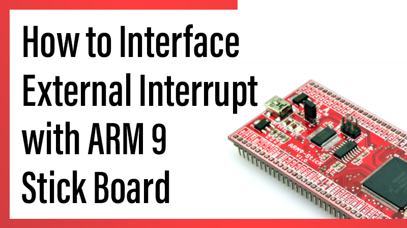
How to Interface External Interrupt with ARM9 Stick Board
ARM9-LPC2929 STICK BOARD
The is specifically designed to help students to master the required skills in the area of embedded systems. The board is designed in such way that all the possible features of the microcontroller will be easily used by the students. The board supports Keil µVision 4 compilers with Keil ULink2.
NXP Microcontroller,ARM9-LPC2929 stick board is proposed to smooth the progress of developing and debugging of various designs encompassing of speed 32-bit Microcontrollers. It integrates CAN, LIN, UART, ADC, PWM, I2C, SPI, Timer, Interrupt etc., to create a stand-alone versatile test platform.
ARM9 Stick Board having more no of I/O line for user access able. Its consists of 64 GPIO pins, CAN0/1, LIN1, I2C0/1, UART0/1, SPI0/1, USB, ADC0/1/2, PWM, Timer and more features. Users can easily access the controller and develop more application by using ARM9 Stick Board.
Interrupts in LPC2929
The ARM9_LPC2929 contains a very flexible and powerful Vectored Interrupt Controller to interrupt the ARM processor on request.
Key Features in Interrupt
- Level-active interrupt request with programmable polarity.
- 56 interrupt request inputs.
- Software interrupt request capability associated with each request input.
- Interrupt request state can be observed before masking.
- Software-programmable priority assignments to interrupt requests up to 15 levels.
- Software-programmable routing of interrupt requests towards the ARM-processor Inputs IRQ and FIQ.
- Fast identification of interrupt requests through vector.
- Support for nesting of interrupt service routines.
Circuit Diagram for Interrupt Test in ARM9 Stick Board
On Board Circuit Diagram
Output for Interrupt Test
1. Main Function – Blinking LED Continuously (P1.5 and P1.6)
2. Interrupt Function –Blink the LED 5 times (P3.0 and P3.1)
Normally the main function running continuously. The Interrupt function will run when press the interrupt switch in the on board.
C Program for External Interrupt in ARM9 Stick Board
Title: Program for External Interrupt
#include

#include


void DelayMs(unsigned int);

void ER_Init(void);


int main (void) // Main function

{

GPIO1_DR |= 0x60; //Initilize led direction port

GPIO3_DR |= 0x03; //Initilize led direction port

ER_Init(); //Initilize lnterrupt function

while(1)

{

GPIO1_OR |= 0x60; // set as High

DelayMs(500);

GPIO1_OR &= ~ 0x60; // set as Low

DelayMs(500);

}

}

void ER_Init(void)

{

SFSP2_26 = (0x01<<2)|(0x03<<0); /* Digital no PU and PD, func. 3. */


ER_APR = (0x0<<6); /* EINT6 is edge trigger, rising edge. */

ER_ATR = (0x0<<6);

ER_INT_CLR = 0x7FFFFFF;

ER_MASK_CLR = 0x7FFFFFF;


/* Setup Event Router interrupt generation */

INT_REQUEST_27 = (1 << 28) | /* Enable setting of priority level */

(1 << 27) | /* Enable setting interrupt target */

(1 << 26) | /* Write enable of new settings */

(1 << 16) | /* Enable interrupt request */

(1 << 8) | /* Interrupt target is IRQ interrupt */

(15 << 0) ; /* Priority level 15, disable nesting */

ER_MASK_SET |= (0x01<<6); /*Enable Interrupt */ return;

}

void ER_Handler (void) __irq /* Interrupt Function */

{

if( ER_PEND & (0x01<<6))

{

unsigned int i;

for(i=0;i<5;i++)

{

GPIO3_OR |= 0x03;;

DelayMs(1000);

GPIO3_OR &= ~0x03;;

DelayMs(1000);

}

ER_INT_CLR = (0x01<<6); /* Clear interrupt status */

}

}

void DelayMs(unsigned int Ms) //Delay Definition

{

int delay_cnst;

while(Ms>0)

{

Ms--;

for(delay_cnst = 0;delay_cnst<1200;delay_cnst++);

}

}


