How to Interface ARM9 Stick with LCD
ARM9-LPC2929 STICK BOARD
The is specifically designed to help students to master the required skills in the area of embedded systems. The board is designed in such way that all the possible features of the microcontroller will be easily used by the students. The board supports Keil µVision 4 compilers with Keil ULink2.
NXP Microcontroller,ARM9-LPC2929 stick board is proposed to smooth the progress of developing and debugging of various designs encompassing of speed 32-bit Microcontrollers. It integrates CAN, LIN, UART, ADC, PWM, I2C, SPI, Timer, Interrupt etc., to create a stand-alone versatile test platform.
having more no of I/O line for user access able. Its consists of 64 GPIO pins, CAN0/1, LIN1, I2C0/1, UART0/1, SPI0/1, USB, ADC0/1/2, PWM, Timer and more features. Users can easily access the controller and develop more application by using
.
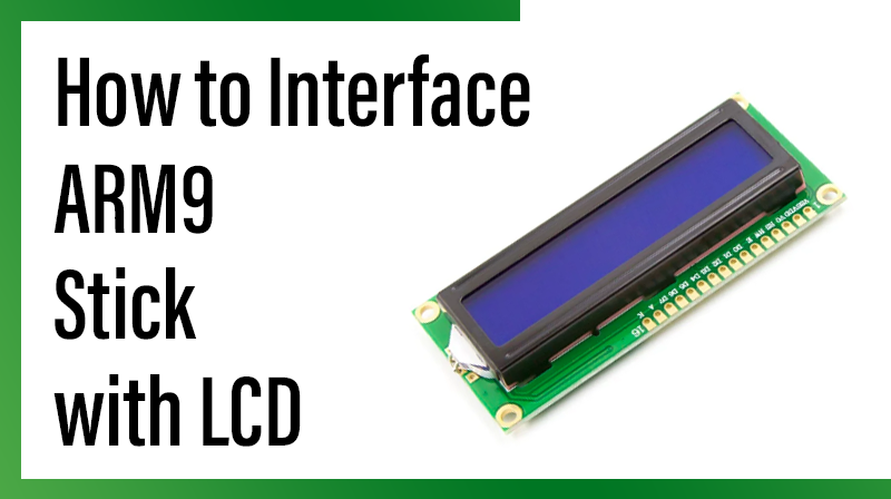
LCD (Liquid Crystal Display)
Liquid Crystal Display also called as LCD is very helpful in providing user interface as well as for debugging purpose. A liquid crystal display (LCD) is a flat panel display that uses the light modulating properties of liquid crystals (LCs). LCD Modules can present textual information to user.
Interfacing LCD
The circuit and Pin diagram shows how to interface the LCD to microcontroller. The 2×16 character LCD interface card with supports both modes 4-bit and 8-bit interface, and also facility to adjust contrast of LCD through trim pot (R1).
In 8-bit interface 11 lines needed to create 8-bit interface; 8 data lines (D0 – D7), three control lines, address bit (RS), read/write bit (R/W) and control signal (EN).
In 4-bit interface 7 lines needed to create 4-bit interface; 4 data line (D0 – D3), three control lines, address bit (RS), read/write bit (R/W) and control signal (EN).
Circuit and Pin Diagram for ARM9 Stick Interface with LCD

Example for ARM9 Stick Board Interface with 8 bit LCD

C Program to display a text in LCD using
Title: Program to 8 bit LCD display
#include  //Register Description Header for LPC2929
#define RS 0x0020 // Register Select
#define RW 0x0040 // Read Write Select
#define EN 0x0080 // Enable
#define D7 0x8000 // Data Line 7
#define D6 0x4000 // Data Line 6
#define D5 0x2000 // Data Line 5
#define D4 0x1000 // Data Line 4
#define D3 0x0400 // Data Line 3
#define D2 0x0300 // Data Line 2
#define D1 0x0200 // Data Line 1
#define D0 0x0100 // Data Line 0
void lcd_cmd (char);
void lcd_data (char);
void lcd_initialize (void);
void lcd_display (void);
void LCD4_Convert(char);
char cmd[4] = {0x38,0x0C,0x06,0x01}; // LCD Comments
char msg[] = {" ARM STICK V1.0"}; // First Line of LCD
char msg1[]= {" WELCOMES YOU"}; // Second Line of LCD
int main(void) // Main Function
{
GPIO3_DR = 0xFFFF; // P3.0 to P3.15 select as Input Direction
lcd_initialize();
lcd_display();
while(1);
}
void delay(int n) // Delay function
{
unsigned int i,j;
for(i=0;i<n;i++)
{
for(j=0;j<4000;j++)
{;}
}
}