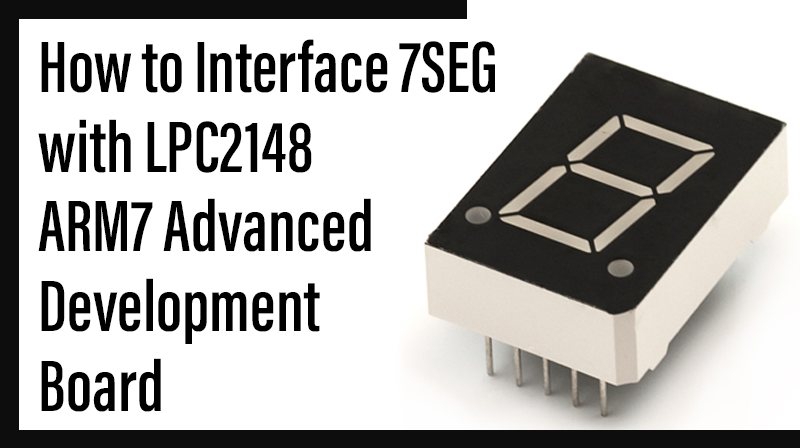
How to Interface 7SEG with LPC2148 ARM7 Advanced development board
The ARM7 LPC2148 Advanced Development Boardis specifically designed to help students to master the required skills in the area of embedded systems. The kit is designed in such way that all the possible features of the microcontroller will be easily used by the students. The kit supports in system programming (ISP) which is done through serial port.
NXP’s ARM7 (LPC2148), ARM Advanced Development Board Kit is proposed to smooth the progress of developing and debugging of various designs encompassing of High speed 32-bit Microcontrollers.
Seven Segment Display
A seven segment display is the most basic electronic display device that can display digits from 0-9. The most common configuration has an array of eight LEDs arranged in a special pattern to display these digits. They are laid out as a squared-off figure ‘8’.
Interfacing Seven Segment Display
Fig. 1 shows how to interface the seven segments with microcontroller. A seven segment is generally available in ten pin package. While eight pins correspond to the eight LEDs, the remaining two pins (at middle) are common and internally shorted. These segments come in two configurations, namely, Common cathode (CC) and Common anode (CA).

Interfacing Seven Segment with LPC2148
We now want to display a four digit number in LPC2148 Advanced Development Board by using seven segment displays. The seven segment display is connected with LPC2138 controller.
In LPC2148 Advanced Development Kit, 4 nos. of common anode seven segment displays are controlled by seven segment drivers.
Pin Assignment with LPC2138
Circuit Diagram to Interface 7 segment with LPC2148

Source Code
The Interfacing seven segment displays with LPC2148 program is very simple and straight forward, which display a four digit number in seven segment display .The C programs are developed in Keil software. Here we are increment a counter and display this value loaded into seven segment driver in LPC2148 ARM Advanced Development Board.
C Program to 7 Segment Display using LPC2148
*************************************************************************************************
Title : Program to Seven Segment display
*************************************************************************************************
#include <LPC214x.h>
#include <stdio.h>
#include "7SEG.H"
unsigned int thou,hun,ten,single;
unsigned int x;
void main(void)
{
PINSEL0 = 0;
PINSEL1 = 0;
PINSEL2 &= 0x0000000C;
IODIR0 |= 0x0F << 10 ;
// P0.10 - P0.13 Control Lines IODIR1 |= 0xfF << 16;
// P1.16 - P1.23 are Outputs while(1)
{
if(x == 300)
{ x=0; single++;
if(single>9)
{
single=0;
ten++;
if(ten>9)
{
ten=0;
hun++;
if(hun>9)
{
hun=0;
thou++;
if(thou>9) thou=0;
}
}
}
}
x++;
Segment_Disp(&IOPIN1, 16,thou, hun, ten, single);
}
}
void DelayMs(unsigned int count)
{
unsigned int i,j;
for(i=0;i<count;i++)
{
for(j=0;j<3000;j++);
}
}
To compile the above C code you must need the KEIL software. They must be properly set up and a project with correct settings must be created in order to compile the code. To compile the above code, the C file must be added to the project.
In KEIL, you want to develop or debug the project without any hardware setup. You must compile the code for generating HEX file. In debugging Mode, you want to check the port output without LPC2148 Advanced Development Board.
The Flash Magic software is used to download the hex file into your microcontroller IC LPC2148 through UART0.
Testing the I2C – Seven segment with LPC2148
Give +3.3V power supply to LPC2148 Advanced Development Board; the four seven segment display is connected with the LPC2148 Advanced Development Board. First check the entire seven segments LED’s are properly working or not. Here we are display just 1234 in four seven segment. The entire seven segments receive it through I2C & display it in order.
If any data is not coming in seven segments, then you just check the entire seven segments LED’s are working or not. Change the seven segment driver IC & Check the I2C connections. Check the four seven segments connections. Otherwise you just check the code with debugging mode in KEIL. If you want to see more details about debugging just see the videos in below link.
☞How to Create & Debug a Project in KEIL.
General Information
☞For proper working use the components of exact values as shown in Circuit file. Wherever possible use new components.
☞Solder everything in a clean way. A major problem arises due to improper soldering, solder jumps and loose joints.
☞Use the exact value crystal shown in schematic.
☞More instructions are available in following articles,
How to Interface Keypad with LPC2148 – ARM7 Advanced Development Board
How to Interface UART with LPC2148 ARM7 Advanced development board