How to assemble and drive Robot Car using Brainsense (BCI) / Neurosky Mindwave Mobile
₹14,160.00
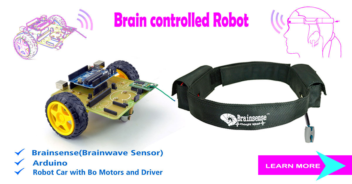
The human brain is the central organ of the human system .The brain sense robot car is interesting to all type of people, to measure their concentration and piece level of mind with our brain sense head band. Our bio-sensor band digitize brain wave signals to power the user- interface of computers, game and health application. The brain sense measure brainwaves from the forehead.
100 in stock
Description
Introduction
The human brain is the central organ of the human system .The brain sense robot car is interesting to all type of people, to measure their concentration and piece level of mind with our brain sense head band. Our bio-sensor band digitize brain wave signals to power the user- interface of computers, game and health application. The brain sense measure brainwaves from the forehead.
Building the Chassis
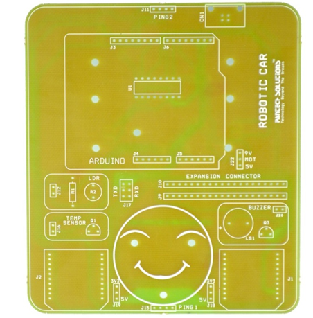
Before programming anything, we’ll build the chassis for the robot. Basically it’s a traditional rover robot structure with two Dc motors in the back and one caster in the front. To make it suitable for mind-controlling needs, we’ll add a Bluetooth for wireless communication and LED indications on the top. We use a Screw Shield for the Arduino, to make adding components and wires easy. Fig 1-1 shows the design of the chassis. Here’s how all the major components will work together to create a working robot:
Arduino
This is the brains of the project. It is essentially a small embedded computer with a brain (a microcontroller), as well as header pins that can connect to inputs (sensors) and outputs (actuators).
Chassis
This holds everything together. It’s essentially the platform for the robot.
DC Motors
These are motors that can be connected directly to the Arduino without the need for any additional hardware (such as a motor shield). The Arduino communicates with them by sending pulses to control speed and direction.
Caster wheel
Because we’ll be turning the robot by varying the speed and direction of the servos, which are fixed in place, we need one wheel that pivots nicely. A furniture caster is perfect for this, and the robot ends up being able to rotate in place.
Screw Shield
Screw Shield adds “wings” with terminal blocks to both sides of Arduino. Terminal blocks have screws, so you can attach one or more wires firmly
to any pin. This prevents wires from popping out, which makes building
and coding the robot much easier.
Brain Sense
Brain Sense measures your brain Waves from EEG signal and transmits the results of attention and meditation to Arduino.
Fig 1.1: Blueprint of the chassis
Tools and Parts
Here we list the parts and tools needed to make the robot
PARTS
Figure 1-2 shows all the parts you need for this project.
Fig: 1.2: Parts
☞Brain Sense sensor or Neurosky mindwave mobileas a mind reading device
☞Arduino Uno
☞DC motor
☞AA Battery(6v-4nos)
☞Battery Holder
☞Wheels
☞USB connector(B- type)
☞Male and Female Headers
☞DC motor Driver(L293D)
☞L-brackets with 3 mm holes
☞Free Wheel
☞Connecting wires and jumpers
TOOLS
☞Hot glue gun
☞Soldering iron and solder
☞Pliers
☞Screwdriver
☞Driller
☞Screws
☞Multimeter.
Fig 1.3:Tools
DC Motors
DC motors will be moving the wheels of our robot. The most usual type of DC have limited rotation. They are used when you need to turn the motor to a specific angle. In our robot, we only need to control speed and direction. And, of course, the motor needs to be able to turn freely. Continuous rotations DC are made for this. Almost any servo can be modified to continuous rotation, but it’s easier to buy a ready-made version.
The Parallax (Futaba) continuous rotation DC is perfect for our needs. This allows identical centring of two DC effortlessly. You’ll notice how handy this is later, when we program the movements for the robot.
Fig 1.4: DC motor and L brackets
Attaching DC Motors
We’re going to use regular L-brackets to attach the DC motors. Attach two brackets to each servo with screws if you can’t find suitable L-brackets, you can make them from metal strips. For example, you could salvage some strips from an old typewriter, drill holes that match your servo, and bend them to a 90° angle in the middle.
Fig1.5: L-bracket attached to DC Motor
Chassis
For the chassis you’ll need something that is robust enough to hold the robot together and can be shaped easily. Plywood, acrylic, or metal plate (Figure 1-3) works well.
Fig 1.6:FR4 sheet (Epoxy Resin)
Our material of choice is FR4 (epoxy resin) It’s light, easy to cut, strong, and good looking. Best of all it happened to be free. Because it’s lightweight and flat, it’s used for printing advertising signs.
Fig 1.7: Printed circuit Plan
Even if you don’t have a sign-making store as your neighbour, you could find other useful material thrown away. For example, you shouldn’t have any trouble finding a metal plate from computer parts or plywood from furniture. Choose a material that is easily available for you and that is comfortable to process with your tools and skills.
Fig1.8: Planed chassis completed with IC base, headers
Making Holes
The easiest way to get the holes where you want them is to hold the target object as a stencil and mark spots with a pen. (Figure 1-9).
Fig 1.9: After making hols for battery holder
First, mark the DC motor bracket places on both sides of the robot. The back wheel will be mounted centred in the back of the chassis. Place the Arduino on the top of the Robot so that the screw holes don’t overlap the back wheels’ holes. One more holes needed for battery holders placements.
Next we’ll drill the holes, but first, its hammer time. Always use a nail punch and a hammer to make a small starting hole before drilling metal
Fig 1.10: DC Motor attached
Wheels
There’s plenty of choice for the wheels (Figure 1-5). Just don’t pick any that are too heavy, and make sure that you’ll be able to make the holes for the DC motor horn attachment. For our robot, we salvaged tires from a remote controlled car.
Fig1.11: Selection of wheels
Drill two 3 mm holes through both DC motor horns and the wheel rim. Secure the DC motor horns to the wheel rims with 3×10 mm screws. Push the DC motor horns on the DC motor shaft and tighten them in place with 3×18 mm woodscrews(Figure 1-6).
Fig1.12: DC Motor shaft attached to tire rim
Battery Holder
A simple 4×A battery holder placed on the back of the chassis. Drill the hole in the middle Put a 3x10mm screw through the hole and mounts the battery holder to the chassis. (Figure 1-7).
Fig1.13: AAA Battery with Battery holder
Bluetooth
Bluetooth module is used to communicate with brain sense and Arduino via wireless manner. One Bluetooth module is connected with top of our chassis and another one is connected with brain sense band (Figure 1-8).
Fig: 1.14: Blue Bee HC-05 Module
Fig1.15:Arduino attached with chassis
Fig1.16: Arduino and Bluetooth attached with chassis
Brain Sense Band
Our Brain Sense band contains EEG module (TGAM1-R2.8) and Bluetooth module (hc-05) with a electrode. It is placed on forehead of the user to measure their brainwaves and to power the user interface of robot.
Fig1.17: Brain Sense band with Bluetooth
Screw Shield Holds Wires in Place
Loose wires are probably the most annoying thing while building a prototype. Arduino’s header pins can’t hold the jumper wires securely. Especially when your robot is moving, wires pop out constantly. Luckily the Screw Shield pretty much solves this problem.
Screw Shield adds “wings” with terminal blocks to both sides of Arduino. Terminal blocks have screws so you can attach one or more wires firmly to any pin.
You have to do some soldering when building the Screw Shield, but it will pay off later on. As an added bonus, you’ll get nice and relatively easy soldering practice.
This completes your robot chassis! You now have a moving robot platform. In the next chapter, you’ll be coding the mind-controlled robot part by part. What other projects could you do with your new robot chassis
Fig1.18: The Mind controlled robot is ready to be programmed
Circuit Diagram
The code that controls your robot is simple. Well, it’s simpler than one would expect for a sci-fi trick like mind control.
A simplified, pseudo code version of your robot would be as follows:
void loop ()
{
while (line Detected ()) turn (); //
forward (get Attention ()); // }
Then the robot goes forward. The speed is read from the EEG headband. Rinse and repeat. In this coding part of the book, you’ll write each part of the code that makes your robot tick.
Moving
Continuous rotation DC motors are motors you can easily control. With continuous rotation DC motor, you can only control the speed (forward, stop, back).
There are three wires going to a DC motor: red (positive), black (ground), to control a DC motor.
Connect DC motor
Let’s start by connecting DC motor to Arduino. To keep the solders in your DC motor intact,
Now connect the wires to Arduino. You can connect both the left and right DC motor away.
Then Arduino data line (GPIO) is given to motor driver (L2930) and then it is given to pins of motor driver. After that output of driver is given to input of the motor
Fig2.1:Connection of Arduino with Bluetooth
The transmitter and receiver of the Arduino is given to blue bee Bluetooth fig2.1
Fig2.2: Connection with Arduino and Bluetooth
————————————————————————————————————-
Note: Every GND symbol means a connection to Arduino GND pin, which is also connected to the black 0V GND wire of the battery. This saves the trouble of having a circuit diagram full of wire going to ground.
————————————————————————————————————-
Configuration settings
Steps to interface Brain Sense with Arduino
Find the Serial number of your Brain Sense Headband
1.Select your Brain Sense Headband
Right click → Properties → Bluetooth →
Then know your Unique Identifier Number (Note it)
Example: This band Unique no =98d3,31,302424
Diagram for HC-05 Bluetooth module with Arduino
Method 1 for AT Commands
Fig2.3:Connection of Arduino with Bluetooth for pairing Brainsense or mindwave mobile with Bluetooth
————————————————————————————
Note: Here the Arduino Board used only for USB to UART converter.
So don’t want to download any source code (Sketch) to board.
Modes of HC-05 Bluetooth module:
How to HC-05 Module Enter into Command mode:
Press and Hold the Push switch in HC-05 Module at few secs, when its power ON (In between OFF state to ON state).
If HC-05 Module in Command mode means, the LED blink at low toggle (blinking slowly).
Baud rate for Command Mode
In command mode the HC-05 Module works in 38400 baud rate (fixed Baud rate).
How to HC-05 Module Enter into Data mode:
In default state, the HC-05 Module works as a Data mode operation.
If HC-05 Module in Data mode means, the LED blink at High toggle.
Baud rate for Data Mode
In Data mode the HC-05 Module works in variable Baud rate.
AT Commands for HC-05 Module Initialize for Brain Sense
First Enter into command mode, after then enter the following AT commands for HC-05 Module to communicate our Brain Sense Headband.
☞.AT+NAME=”PANTECH”
☞.AT+UART=”57600,0,0”
☞.AT+ROLE=”1”
☞.AT+PSWD=”1234”
☞.AT+CMODE=”0”
☞.AT+BIND=”XXXX,YY,ZZZZZZ”(MindwaveUniqueNumber)
☞.AT+IAC=”9E8B33”
☞.AT+CLASS=”0”
☞.AT+INQM=”1,9,48”
Verification commands for HC-05 Module
1.AT
OK
2.AT+UART?
+UART:57600,0,0
OK
2.AT+ROLE?
+ROLE:1
OK
3.AT+PSWD?
+PSWD:0000
OK
4.AT+CMODE?
+CMODE:0
OK
5.AT+BIND?
+BIND:9cb7:0d:89e51c
OK
6.AT+IAC?
+IAC:9E8B33
OK
7.AT+INQM?
+INQM:1,9,48
OK
—————————————————————————————————————-
Note: For using above AT commands don’t use “(Double quotes) only enter In-between commands from double quotes.
After the end of every command press “Enter Key”
—————————————————————————————————————-
Open serial communication software
(Here we have to use Flash magic software)
1.Select your Port and set Baud rate is 38400
Enter the AT com
2.Enter the AT commands (Verification)
Some Tips about HC-05 Module Configuration
1. HC-05 Module configure as Mater device and Brain Sense Headband act as Slave device
☞And the HC-05 Module was configuring as Specific address mode. Therefore it’s Pair with only the specific device.
☞Here the specific device is our Brain Sense Headband (Using BIND AT command, we configured the Brain Sense unique number to HC-05).
☞So the Brain Sense and HC-05 module automatically paired, when we switch ON the both device.
Steps to wear a Brain Sense band on forehead
Fig2.4: Quick start guide
Fig2.5: Steps to Turn on Brain Sense
Fig2.5: Steps to wear Braine sense
Fig2.6: Signals and Status meter measured by neuro view
NeuroSky Protocol
How do you begin when faced with an unknown protocol? We did some Googling, and found that the NeuroSky reference documentation and more was available on the NeuroSky website. For example, see “Mind Wave and Arduino” (NeuroSky 2011), “Mindset Communications Protocol” (NeuroSky 2010), and “arduino_tutorial” in the NeuroSky wiki (http://developer.neuro sky.com/docs/doku.php?id=start).
The NeuroSky dongle communicates over the serial port. We have wires going to Arduino RX and TX.
Every packet is of this format: sync (170 170), payload length, payload, and a checksum (see Table2.1)
Table 2-1. NeuroSky packet
|
Meaning |
Example |
Comment |
|
Sync |
170 170 |
Always the same |
|
Payload length
|
4
|
Most common length in this project |
|
Payload |
486 |
4 attention, value 86/100 = 86% |
|
Payload cont. |
20 |
2 poor signal, value 0 signal OK |
|
Checksum |
163 |
255–(sum of each payload byte) |
Even though the reference documentation saved us the tedious work of reverse engineering the protocol, there were surprises around the corner. Coping with serial buffer overflow, long delays caused by moving parts, and doing voltage level changes without additional circuits were problems to solve.
62 Make a Mind-Controlled Arduino Robot www.pantechsolutions.net NeuroSky, the manufacturer of Mind Wave, provides excellent documentation. See “Mindset Communications Protocol” and “Mind Wave Dongle Communications Protocol.” Some code samples on the Web use everyday decimal format (170), but some use hexadecimal (0xaa or just AA). We’ve compiled a list of the most common code numbers You can also convert numbers with Python. Just start Python at the command line and you’ll get an interactive console where you can type things like hex(170) or 0xaa. Or you can use http://www.wolframalpha.com or Google. Most of the NeuroSky protocol control characters we use are outside ASCII. The last ASCII printable character is 126 tilde ~; the last ASCII character is 127 DEL.
Fig2.7: Finished mind-controlled robot
Additional information
| Weight | 1.000000 kg |
|---|





Reviews
There are no reviews yet.