UART Interface with Spartan3an FPGA Starter Kit
UART Stands for Universal Asynchronous Transmitter Receiver. The function of UART is conversion parallel data (8 bit) to serial data. UART transmit bytes of data sequentially one bit at a time from source and receive the byte of data at the destination by decoding sequential data with control bits. As the entire processes require no clock input from source hence it is termed as asynchronous communication.
Baud Rate
In the UART communication data transmission speed is measured by Baud Rate. Baud rate describes the total number of bit sent through serial communication. It includes Start bit, Data byte, Parity bit and Stop bit. Transmitter and receiver need to be maintained in the baud rate. For example Spartan3an FPGA Starter Kit transmit data at the baud rate of 9600 and at the receiving end PC need to be set with same baud rate using HyperTerminal or TeraTerminal.
Packet of Data in Serial Communication
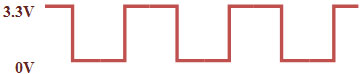
Serial data communicate on FPGA side range in 0 to 3.3v. Logic 0 is represented by 0v. Logic 1 is represented by 3.3v
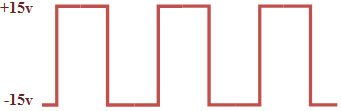
On PC Side RS232 Port voltage range from -15v to +15v. Logic 0 is represented by +3v to 15v. Logic 1 is represented by -3v to -15v.
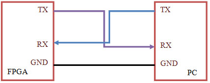
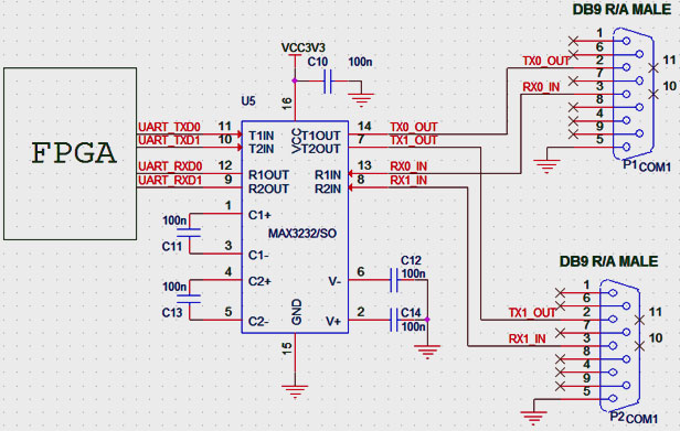
In order to communicate between FPGA and PC with different voltage level, MAX3232 Driver IC is required. It consists of 2 channel transmitter and Receiver.
Serial communication
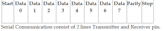
The data communication of UART is made by 11 bit blocks
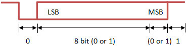
The wave form showed the protocol of the UART. Here the ‘0’ bit represent as start bit which is initiated the serial communication. The start bit must be ‘0’. The next 8 bit’s are data bit. The LSB bit of data goes as first bit continue it sent other 7 bits. The 10th bit is a parity bit which is used to identify error in the communication. The parity bit is either 0 or 1 which is depending on the number of 1’s present in transmission. If even parity is used, the number of bit must be even. If odd parity is used, the number of bit must be odd. The speed of transmission is fixed which is measured by baud rate. The last bit is stop bit which must be ‘1’.
Note: The parity bit is not necessary which is optional.
Transmission delay
The transmission rate is measured by bits per second. Each bit has a fixed time duration while transmission. The transmission delay for each bit 104.16 μs which is constant till the end of communication.
Example
The baud rate is 9600.
Transmission delay =1/9600 =104.16 μs.
RS 232 connector and cable
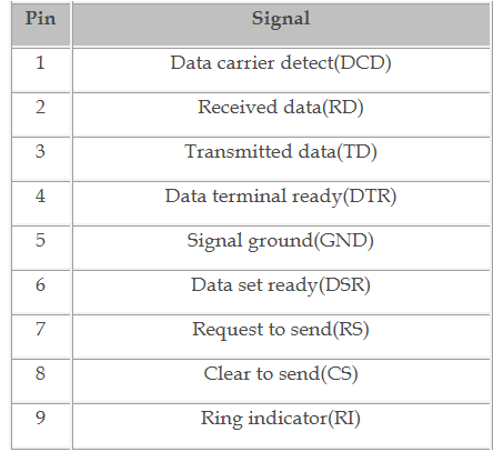
RS 232 connector is used to establish connection between Spartan3an FPGA Starter Kit and PC. It is either male or female connector. Here we use only female to female connector. RS 232 connector has only 9 pins, even though the only 3 pins are enough to make a transmission between PC and FPGA such as RD,TD and GND.
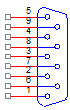
Table 1
RS232 interface using Max3232 Driver IC with Spartan3an FPGA Starter Kit
UART Placement in Spartan3an FPGA Starter Kit
In this article, 3 example codes are provided to demonstrate the UART Communication.
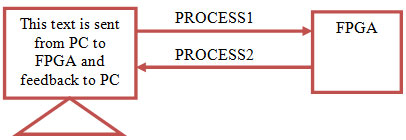
1st VHDL Code describes Transmitting data from PC HyperTerminal to Spartan3an FPGA Starter Kit and feedback to PC at 9600 Baud Rate.
This Code consists of Clock and Reset input. Clock running at 50MHz and Reset is assigned to Slide switch to enable or disable Serial Communication. Din and Do are transmit and receive of the FPGA. The Functionality of this code can be explained by 2 process statements. Process 1 involves transmission of data from PC to FPGA and stores them in array. Process 2 involves retransmission of data stores in FPGA array to PC.
VHDL Code for Serial Communication Transmitting data from PC to Spartan3an FPGA Starter Kit and feedback to PC at 9600 Baud Rate
library IEEE;

use IEEE.STD_LOGIC_1164.ALL;

use IEEE.STD_LOGIC_ARITH.ALL;

use IEEE.STD_LOGIC_UNSIGNED.ALL;


entity uart is

port (      clk   : in std_logic;      -----system clock i/p

            reset : in std_logic;      -----switch input

            din   : in  std_logic;     -----fpga receive i/p

            do    : out std_logic);   ------fpga transmit o/p

end uart;


architecture Behavioral of uart is

type state is (ready,b0,b1,b2,b3,b4,b5,b6,b7,b8);   ----fsm for receive

signal ps : state := ready;

type state1 is (ready1,b01,b11,b21,b31,b41,b51,b61,b71,b81);  -----fsm for transmit

signal ps1 : state1 := ready1;

signal start,stop : std_logic := '0';

signal store : std_logic_vector(7 downto 0) := "00000000";  ----storing of recived value

begin

process(reset,clk)

variable i : integer := 0 ;

begin

if reset = '1' then

if clk'event and clk = '1' then

if ps = ready then     ----logic to detect the transmission start

start <= din;

end if;

if start = '0' then

ps <= b0;

elsif start = '1' then

ps <= ready;

end if;

------------------------------------------1

if ps = b0 then

store(0) <= din;        -----receive and store of each bit

i := i + 1;

ps <= b0;

if i = 5209 then    -----timing delay to receive bit

i := 0;

ps <= b1;

end if;

end if;

------------------------------------------2

if ps = b1 then

store(1) <= din;

i := i + 1;

ps <= b1;

if i = 5209 then

i := 0;

ps <= b2;

end if;

end if;

-----------------------------------------3

if ps = b2 then

store(2) <= din;

i := i + 1;

ps <= b2;

if i = 5209 then

i := 0;

ps <= b3;

end if;

end if;

----------------------------------------4

if ps = b3 then

store(3) <= din;

i := i + 1;

ps <= b3;

if i = 5209 then

i := 0;

ps <= b4;

end if;

end if;

---------------------------------------5

if ps = b4 then

store(4) <= din;

i := i + 1;

ps <= b4;

if i = 5209 then

i := 0;

ps <= b5;

end if;

end if;

---------------------------------------6

if ps = b5 then

store(5) <= din;

i := i + 1;

ps <= b5;

if i = 5209 then

i := 0;

ps <= b6;

end if;

end if;

---------------------------------------7

if ps = b6 then

store(6) <= din;

i := i + 1;

ps <= b6;

if i = 5209 then

i := 0;

ps <= b7;

end if;

end if;

--------------------------------------8

if ps = b7 then

store(7) <= din;

i := i + 1;

ps <= b7;

if i = 5209 then

i := 0;

ps <= b8;

end if;

end if;

--------------------------------------9

if ps = b8 then

stop <= din;

i := i + 1;

ps <= b8;

if i = 5209 then

i := 0;

ps <= ready;

end if;

end if;

-------------------------------------10

end if;

end if;

end process;

----------------------------------------------------------------------transmit

process(reset,clk)

variable i : integer := 0 ;

begin

if reset = '1' then

if clk'event and clk = '1' then

if ps1 = ready1 then

if start = '0' then     -----logic to indicate the communication to the partner

do <= '0';

i := i + 1;

ps1 <= ready1;

if i = 5209 then

i := 0;

ps1 <= b01;

end if;

elsif start = '1' then

ps1 <= ready1;

end if;

end if;

------------------------------------------1

if ps1 = b01 then

do <= store(0);     ----transmission of each bit

i := i + 1;

ps1 <= b01;

if i = 5209 then    ----timing delay for transmission of each bit

i := 0;

ps1 <= b11;

end if;

end if;

------------------------------------------2

if ps1 = b11 then

do <= store(1);

i := i + 1;

ps1 <= b11;

if i = 5209 then

i := 0;

ps1 <= b21;

end if;

end if;

-----------------------------------------3

if ps1 = b21 then

do <= store(2);

i := i + 1;

ps1 <= b21;

if i = 5209 then

i := 0;

ps1 <= b31;

end if;

end if;

----------------------------------------4

if ps1 = b31 then

do <= store(3);

i := i + 1;

ps1 <= b31;

if i = 5209 then

i := 0;

ps1 <= b41;

end if;

end if;

---------------------------------------5

if ps1 = b41 then

do <= store(4);

i := i + 1;

ps1 <= b41;

if i = 5209 then

i := 0;

ps1 <= b51;

end if;

end if;

---------------------------------------6

if ps1 = b51 then

do <= store(5);

i := i + 1;

ps1 <= b51;

if i = 5209 then

i := 0;

ps1 <= b61;

end if;

end if;

---------------------------------------7

if ps1 = b61 then

do <= store(6);

i := i + 1;

ps1 <= b61;

if i = 5209 then

i := 0;

ps1 <= b71;

end if;

end if;

--------------------------------------8

if ps1 = b71 then

do <= store(7);

i := i + 1;

ps1 <= b71;

if i = 5209 then

i := 0;

ps1 <= b81;

end if;

end if;

--------------------------------------9

if ps1 = b81 then

do <= '1';

i := i + 1;

ps1 <= b81;

if i = 5209 then

i := 0;

ps1 <= ready1;

end if;

end if;

-------------------------------------10

end if;

end if;

end process;

end Behavioral;
2nd VHDL Code simply describes transmitting data from Spartan3an FPGA Starter Kit to PC.
This Code consists of Clock input and Transmitter output from Spartan3an FPGA Starter Kit. Clock running at 50MHz. The VHDL Code for UART simply transmits data stored in the FPGA to PC. The Clock frequency can be easily modified using the parameter system_speed. Also Baud rate can be changed by modifying the parameter clock_out_speed.
VHDL Code for transmitting data from FPGA to PC
library IEEE;

use IEEE.STD_LOGIC_1164.ALL;

use IEEE.NUMERIC_STD.ALL;


entity uart_transmitter is

port(

clock: in std_logic;

txd: out std_logic);

end uart_transmitter;


architecture Behavioral of uart_transmitter is

constant system_speed: natural := 50e6;


signal baudrate_clock, second_clock, old_second_clock: std_logic;

signal bit_counter: unsigned(3 downto 0) := x"9";

signal shift_register: unsigned(9 downto 0) := (others => '0');

signal char_index: natural range 0 to 18;

component clock_generator

generic(clock_in_speed, clock_out_speed: integer);

port(

clock_in: in std_logic;

clock_out: out std_logic);

end component;


begin

baudrate_generator: clock_generator

generic map(clock_in_speed => system_speed, clock_out_speed => 9600)

port map(

clock_in => clock,

clock_out => baudrate_clock);


second_generator: clock_generator

generic map(clock_in_speed => system_speed, clock_out_speed => 1)

port map(

clock_in => clock,

clock_out => second_clock);


send: process(baudrate_clock)

begin

if baudrate_clock'event and baudrate_clock = '1' then

txd <= '1';

if bit_counter = 9 then

if second_clock /= old_second_clock then

old_second_clock <= second_clock;

if second_clock = '1' then

bit_counter <= x"0";

char_index <= char_index + 1;

case char_index is

when 0 =>

shift_register <= b"1" & x"50" & b"0";---P

when 1 =>

shift_register <= b"1" & x"41" & b"0";---A

when 2 =>

shift_register <= b"1" & x"4E" & b"0";---N

when 3 =>

shift_register <= b"1" & x"54" & b"0";---T

when 4 =>

shift_register <= b"1" & x"45" & b"0";---E

when 5 =>

shift_register <= b"1" & x"43" & b"0";---C

when 6 =>

shift_register <= b"1" & x"48" & b"0";---H

when 7 =>

shift_register <= b"1" & x"20" & b"0";

when 8 =>

shift_register <= b"1" & x"53" & b"0";---S

when 9 =>

shift_register <= b"1" & x"4F" & b"0";---O

when 10 =>

shift_register <= b"1" & x"4C" & b"0";---L

when 11 =>

shift_register <= b"1" & x"55" & b"0";---U

when 12 =>

shift_register <= b"1" & x"54" & b"0";---T

when 13 =>

shift_register <= b"1" & x"49" & b"0";---I

when 14 =>

shift_register <= b"1" & x"4F" & b"0";---O

when 15 =>

shift_register <= b"1" & x"4E" & b"0";---N

when 16 =>

shift_register <= b"1" & x"53" & b"0";---S

when 17 =>

shift_register <= b"1" & x"20" & b"0";---SPACE BAR

when 18 =>

shift_register <= b"1" & x"20" & b"0";--- SPACE BAR

char_index <= 0;

when others =>

char_index <= 0;

end case;

end if;

end if;

else

txd <= shift_register(0);

bit_counter <= bit_counter + 1;

shift_register <= shift_register ror 1;

end if;

end if;

end process;


end Behavioral;


library IEEE;

use IEEE.STD_LOGIC_1164.ALL;

use IEEE.NUMERIC_STD.ALL;


entity clock_generator is

generic(clock_in_speed, clock_out_speed: integer);

port(

clock_in: in std_logic;

clock_out: out std_logic);

end entity clock_generator;


architecture Behavioral of clock_generator is


function num_bits(n: natural) return natural is

begin

if n > 0 then

return 1 + num_bits(n / 2);

else

return 1;

end if;

end num_bits;


constant max_counter: natural := clock_in_speed / clock_out_speed / 2;

constant counter_bits: natural := num_bits(max_counter);


signal counter: unsigned(counter_bits - 1 downto 0) := (others => '0');

signal clock_signal: std_logic;


begin

update_counter: process(clock_in)

begin

if clock_in'event and clock_in = '1' then

if counter = max_counter then

counter <= to_unsigned(0, counter_bits);

clock_signal <= not clock_signal;

else

counter <= counter + 1;

end if;

end if;

end process;


clock_out <= clock_signal;

end Behavioral;
3rd VHDL Code describes Controlling On/Off Spartan3an FPGA Starter Kit interfaced devices such as Relay, Buzzer, LED etc from PC HyperTerminal.
This Code consists of Clock input and Receive input to Spartan3an FPGA Starter Kit and 2 LED output. Clock running at 50MHz. The VHDL Code for UART receives data from PC and ON/OFF LED’s in the FPGA.
VHDL Code for Controlling LED’s interfaced Spartan3an FPGA Starter Kit from PC HyperTerminal
library IEEE;

use IEEE.STD_LOGIC_1164.ALL;

use IEEE.STD_LOGIC_ARITH.ALL;

use IEEE.STD_LOGIC_UNSIGNED.ALL;


entity uart_reciever is

port (       clk   : in std_logic;

             din   : in  std_logic;

             led1     : out std_logic;

             led2     : out std_logic);


end uart_reciever;


architecture Behavioral of uart_reciever is

type state is (ready,b0);

signal ps : state := ready;

type state1 is (st1,st2);

signal ps1 : state1 := st1;

signal start,stop : std_logic;

signal store : std_logic_vector(7 downto 0) := "10101010";

begin

process(clk)

variable i : integer := 0 ;

begin

if clk'event and clk = '1' then

if ps = ready then

start <= din;

end if;

if start = '0' then

ps <= b0;

elsif start = '1' then

ps <= ready;

end if;

------------------------------------------1

if ps = b0 then

i := i + 1;

if i = 2600 then

start <= din;

end if;

if i = 7800 then

store(0) <= din;

end if;

if i = 13000 then

store(1) <= din;

end if;

if i = 18200 then

store(2) <= din;

end if;

if i = 23400 then

store(3) <= din;

end if;

if i = 28600 then

store(4) <= din;

end if;

if i = 33800 then

store(5) <= din;

end if;

if i = 39000 then

store(6) <= din;

end if;

if i = 44200 then

store(7) <= din;

end if;