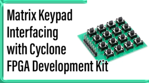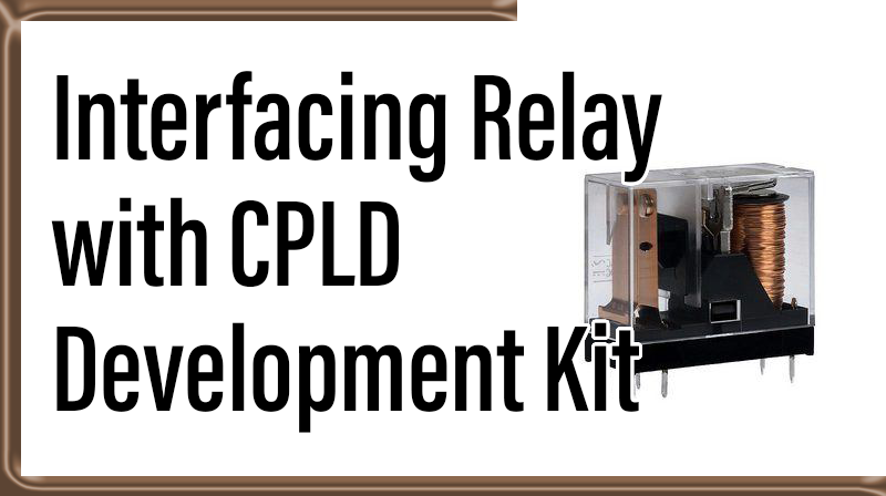
Interfacing Relay with CPLD Development Kit
Interfacing Relay with CPLD Development Kit
Relay is an electromechanical switch which has a wide range of application in industries. It consists of contacts and an electromagnet. Relay makes a bridge between low current and high current device which means electronics to electrical. It is used to control high capacity AC or DC load by low current DC. To control the electrical device through electronics (such as CPLD, microprocessor etc) the sensor and relay are required. And also CPLD cannot able to drive relay directly. Because of the CPLD GPIO capability is 3.3v. So that driver circuit are needed this is made by ULN 2803.
Parts of relay
Any relay has contain these major part in its construction such as
☞Electromagnet
☞Contact
☞Armature
☞Spring
Electromagnet
Electromagnet made of iron core which is wounded by coils. When apply the voltage to the coil which will be magnetic. Hence this is called as electromagnetic.
Contact
The both NO and NC contact are made for connection between the load.
Armature
Armature is a movable magnetic strip. As the supply flow them, it will energize the coil and produce the magnetic field. By the electromagnetic field the strip moves on contact with help of spring.
Spring
Spring is used to control the armature position. When relay is off, the spring is used to pull the armature away. Now the armature will be become to this position.
Working of Relay
Relay consists of an electromagnet, a spring and a contact. The construction of relay is the coil surrounded by an iron core. When apply the voltage to the relay, the electromagnetic field is introduced and the current flows through the coil to ground. Now the armature is pulled by electromagnetic field and the load is driven by relay. When switch off the relay the coil is de-energised and magnetic field is removed. Hence the contact is become to this position. But it operates with limit of current only (which is specified on the relay).
Fig 1: Construction of relay
In CPLD board relay has a three point which are NC (Normally closed), C (Common), NO (Normally open).
In normally open relay the common point is connected to NO contact which means the relay will be in deactivate (relay off) until it activate (relay on). In normally closed relay the common point is connected to NC contact which means the relay will be in activate until it deactivate.
Relay driver
The voltage capability of CPLD GPIO is only 3.3v standard logic level. So the CPLD output cannot drive the relay with 3.3v. Hence the driver circuit is needed to energize the relay. Here the driver circuit helps to increase the output voltage of CPLD for relay.
Type of relay
SPST (Single Pole Single Throw)
These types of relay consist of four terminals. In this four terminals two terminals are used for coil and other two for connect or disconnect the circuit.
SPDT (Single Pole Double Throw)
This type of relay consists of five terminals. In these five terminals two terminals are used for coli, one terminal for common point and remaining two terminals which can be connected to common terminal.
DPST (Double Pole Single Throw)
These types of relay consist of six terminals. In this six terminals two terminals are used for coil and other four for connect and disconnect the two circuits. Because of the relay is made by pair of SPST relay.
DPDT (Double Pole Double Throw)
These types of relay consist of eight terminals. In these eight terminals two terminals are used for coil and other two terminals is a common point for remaining two terminals.
Interfacing relay with CPLD Development Kit
Fig 3: Relay with PTB connector
Relay Placement in CPLD Development Kit
The ULN2803 contain eight input and output which is operated by 5v supply. Here only four pins are needed to make a connection between CPLD and relay. The ULN2803 IC is used to drive the both relay with individual electrical pulse. The relay ON and OFF are shown by the LEDs. PTB connectors have been used to connect load. The voltage range specification has been given on the relay in which voltage it can be operated. The load should be within specification of voltage range of the relay. Otherwise the relay as well as CPLD will be damaged.
Note: should be ensured the capability of the relay before connects the load.
VHDL Code description
This code has been written as to enable the relay simultaneously. The CPLD is operated by 50 MHz and the time is in terms of ns. The time should be converted into in terms of second to enable the relay. So that loop is created for one second. Therefore two relay is operated simultaneously with one second time delay.
VHDL code for relay interface with CPLD
library IEEE;

use IEEE.STD_LOGIC_1164.ALL;

use IEEE.STD_LOGIC_ARITH.ALL;

use IEEE.STD_LOGIC_UNSIGNED.ALL;


entity relay is

port ( clock : in std_logic;

       a     : out std_logic

               );

end relay;


architecture Behavioral of relay is

begin

process(clock)

variable i : integer := 0;

begin

if clock'event and clock = '1' then

if i <= 50000000 then

i := i + 1;

a <= '1';

elsif i > 50000000 and i < 100000000 then

i := i + 1;

a <= '0';

elsif i = 100000000 then

i := 0;

end if;

end if;

end process;

end Behavioral;
User Constraint File
NET "clock"  LOC = "p181"  ;
NET "relay(0)"  LOC = "p125"  ;
NET "relay(1)"  LOC = "p124"  ;