

FPGA Implementation of Multi Channel UART using Spartan3an FPGA Project Kit
Call for Price
To meet modern complex control systems communication demands, the project presents a multi-channel UART controller based on FIFO(First In First Out) technique and FPGA(Field Programmable Gate Array).
Shipping : 4 to 6 working days from the Date of purchase
Package Includes:
-
Complete Hardware Kit
-
Demo Video
-
Abstract
-
Reference Paper
-
!!! Online Support !!!
Description
Abstract
To meet modern complex control systems communication demands, the project presents a multi-channel UART controller based on FIFO(First In First Out) technique and FPGA(Field Programmable Gate Array). The project presents design method of asynchronous FIFO and structure of the controller implemented in Spartan3an FPGA Project kit. This controller is designed with FIFO circuit block and UART (Universal Asynchronous Receiver Transmitter) circuit block within FPGA to implement communication in modern complex control systems quickly and effectively. From the communication sequence diagrams, it is easily to know that this controller can be used to implement communication when master equipment and slaver equipment are set at different Baud Rate. It also can be used to reduce synchronization error between sub-systems in a system with several sub-systems. The controller is reconfigurable and scalable.
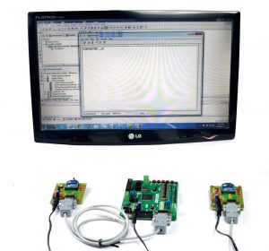
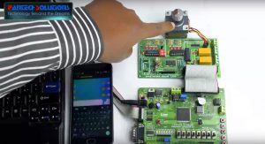
Demonstration Video
Software:
- Xilinx ISE 10.1i or above
Language:
- VHDL, C Code
Hardware:
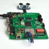
- Spartan3an FPGA Project kit
- USB Cable
- Serial Cable
Block Diagram for FPGA Implementation of Multi Channel UART using Spartan3an FPGA Project kit


Introduction:
In the multi-channel controller, there are different blocks including UART block, Status Detectors, asynchronous FIFOs block and Baud Rate Generator block. Each block has different function in the controller. The first part is UART circuit block. It consists of three parts Receive Circuit, Transmit Circuit and Control/Status Registers. The Transmit Circuit consists of a Transmit Buffer and a Shift Register. Transmit Buffer loads data being transmitted from local CPU. And Shift Register accepts data from the Transmit Buffer and send it to the TXD pin one by one bit. The Receive Circuit consists of a Receive Shift Register and a Receive Buffer. The Receive Shift Register receives data from RXD one by one bit. The Receive Buffer loads data from long-distance MCU and gets it ready for the local PC to read.
The Control Register a special function register is used to control the UART and indicate status of it. According to each bit’s value the UART will choose different kind of communication method and the UART knows what to do to receive or transmit data. FIFOs are used to store data received from the PC and get ready for sub MCUs. When writing data into FIFOs and reading data out of FIFOs we could set different clock domains according to the PC’s and MCUs’ Baud Rate. So it can be used to implement communications between MCUs at different Baud Rate
Flow chart

Spartan3an FPGA Project kit UART Placement

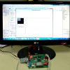
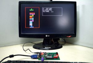
Multi Channel UART using Spartan3an FPGA Project kit Output Image


Additional information
| Weight | 1.000000 kg |
|---|
Reviews
There are no reviews yet.