

FPGA Based patient monitoring System using Spartan3an FPGA Starter Kit
Call for Price
This Project implements FPGA based patient monitoring system using Medical Alert Bracelets offers an empowering option for individuals affected with chronic illnesses or medical conditions who may present more frequently to the ER.
Description
Abstract
This Project implements FPGA based patient monitoring system using Medical Alert Bracelets offers an empowering option for individuals affected with chronic illnesses or medical conditions who may present more frequently to the ER. Trying to identify an unconscious patient or patient who is unable to communicate can lead to delays in treatment. With Medical Alert Bracelets emergency departments improve efficiency while enhancing the level of patient care. If you have a medical condition such as a life threatening food or medicine allergy, a pre-existing medical condition or maybe even a rare blood type, a medical alert bracelet may be the only communication you have to let emergency medical staff know so they can provide the proper treatment for you without potentially doing more harm. RF Transmitter is used as Medical alert Bracelet. Receiver section is equipped with Spartan3an FPGA Starter Kit and RF Receiver TAG.
demonstration Video
Tool required
Software:
- Xilinx ISE 11.1i
- Language: VHDL
Hardware:
- Spartan3an FPGA Starter Kit
- RF module
- PC
Block Diagram for Patient Monitoring using Spartan3an FPGA Starter Kit
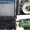
Reader and PC section

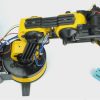
Person Section:

Introduction:
RFID in Healthcare
The term radio frequency identification (RFID) describes a wireless identification technology that communicates data by using radio waves. RFID is now generating significant interest in the marketplace because of its robust application capabilities. Thus, RFID can provide a number of benefits to the healthcare industry, improving overall safety and operational efficiency because it operates without line-of-sight while providing read/write capabilities.
RF Module
The RF module, as the name suggests, operates at Radio Frequency. The corresponding frequency range varies between 30 kHz & 300 GHz. In this RF system, the digital data is represented as variations in the amplitude of carrier wave. This kind of modulation is known as Amplitude Shift Keying (ASK).
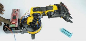
Interfacing RF Module with Spartan3an FPGA Starter Kit
The Spartan-3an board has external RF Module interfacing, indicated as in Figure 4. This RF module comprises of an RF Transmitter and an RF Receiver. The transmitter/ receiver (Tx/Rx) pair operates at a frequency of 434 MHz. An RF transmitter receives serial data and transmits it wirelessly through RF through its antenna connected at pin4 at the rate of 1Kbps – 10Kbps. The transmitted data is received by an RF receiver operating at the same frequency as that of the transmitter. The encoder is used for encoding parallel data for transmission feed while reception is decoded by a decoder. Finally connected with FPGA I/O lines.

Figure 1: RF Transmitter and Reciever
RF Transmitter Pin Description
|
Pin No |
Description |
|
1 |
Ground |
|
2 |
Data |
|
3 |
Power Supply |
|
4 |
Antenna |
RF Receiver Pin Description
|
Pin No |
Description |
|
1 |
Ground |
|
2 |
Data |
|
3 |
No connect |
|
4 |
Power Supply |
|
5 |
Power Supply |
|
6 |
Ground |
|
7 |
Ground |
|
8 |
Antenna |
RF EncoderRF transmitter consists of RF Encoder HT12E IC. It performs Parallel to Serial conversion. HT12E IC encodes 12 bit of Address and Data to RF Transmitter for serial transmission.

Figure 2: RF Encoder HC12E ICRF DecoderRF receiver consists of RF Decoder HT12D IC. It performs Serial to Parallel conversion. HT12D IC decodes 12 bit of Address and Data from RF receiver for parallel reception.

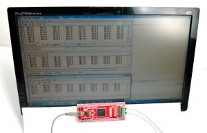
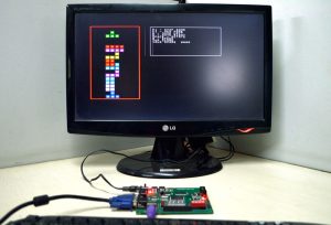
Patient monitoring output image


Conclusion

Proposed System is implemented in Spartan3an FPGA Starter Kit and output is transferred through RS232 and monitored in PC with VB GUI.
Additional information
| Weight | 1.000000 kg |
|---|
Reviews
There are no reviews yet.