

Fiber Optics LED Module
Call for Price
Fiber Optics LED Module
Description
INTRODUCTION
Now we are in the twenty first century, the era of ‘Information technology’ there is no doubt that information technology has an exponential growth through the modern telecommunication systems. Particularly, optical fiber communication plays a vital role in the development of high quality and high-speed telecommunication systems. Today, optical fibers are not only used in telecommunication links but also used in the Internet and local area networks (LAN) to achieve high signaling rates.
Here, Our Fiber optics Light emitting diode module has been uses for study the fiber optic systems. In this module have internal DC source and this module will be supporting external DC voltage also. This module designs for study the optical LED voltage vs current (VI) characteristics, power vs current (PI) and numerical aperture of the optical fiber cable. And this module uses for students to get knowledge about optical components.
PREFACE
Principle of LED
A light-emitting diode LED is a semiconductor diode made by creation of a junction of n-type and p-type materials. Thus, the principle of an LED’s action works precisely the same way that we described the creation of permanent light radiation: the forward-biasing voltage, V, causes electrons and holes to enter the depletion region and recombine. Alternatively, we can say that the external energy provided by V excites electrons at the conduction band. From there, they fall to the valence band and recombine with holes. Whatever point of view you prefer, the net result is light radiation by a semiconductor diode.
Forward Bias Operation

Optical fiber
The transmission medium in fiber-optic communications systems is an optical fiber. The optical fiber is the transparent flexible filament that guides light from a transmitter to a receiver. An optical information signal entered at the transmitter end of a fiber – optic communications system is delivered to the receiver end by the optical fiber.
Model Diagram for Plastic Fiber cable

Fiber cable Properties

TECHNICAL SPECIFICATION
- LED Type : DC coupled Red color
- Source Wavelength : 660nm
- Supply Voltage : +12V DC
- Internal DC Source : 0V to +5V
- External DC Input : 0V to +5V (Below +5V only)
- LED operation mode : Forward Bias
- LED Interface : Self locking Cap
- Supply current : 100 mA (Maximum)
- Fiber Cable Type : 1000 Micron Plastic Fiber Cable
- Core Refractive Index : 1.492
- Cladding Refractive Index : 1.406
- Interface connectors : 2mm socket
FEATURES
- On-board DC source.
- Wider bandwidth link at 660nm.
- Input over voltage protection using active components.
- Wider bandwidth link at 660nm.
- Supporting External DC voltage at variable range (0V to +5V).
- Wider bandwidth link at 660nm.
- Number of test point to study the LED characteristics.
- Wider bandwidth link at 660nm.
Internal DC Source
In this module internal DC source produce variable DC voltage at the range of 0V to +5V.
External DC Input
This module was design to supporting external DC voltage at variable range .Here we will give DC voltage at the range of below +5V.
Light Emitting Diode
Here we were used Optical LED SFH 756V and study this diode characteristics.
Power Supply
In this module need +12V/500mA DC adapter for power supply. That will be converting +5V in on board.
Front Panel Diagram for LED Module

EXPERIMENTAL SECTION
LIST OF EXPERIMENTS
1. Experiment 1:
To Study the VI Characteristics of Optical LED
2. Experiment 2:
To Study the PI Characteristics of Optical LED
3. Experiment 3:
To Study the Numerical Aperture of Optical Fiber Cable
EXPERIMENT – 1: Study the VI Characteristics of Optical LED
Aim
To study VI Characteristics of fiber optical LED
Apparatus Required
- Fiber Optics Light Emitting Diode Module– 01
- Plastic Fiber cable 1 meter – 01
- Multi meter – 01
- Adapter +12V/ DC – 02
- Patch Chords – 04
Procedure
- Connect +12V adapter on LED module.
- Measure the series resistance R.
- Switch (sw1) ON LED Module and Multi meter.
- Connect the multi meter probe, positive to P1 and negative to P2 Ground.
- Now we get a DC voltage output on multi meter and vary the pot meter min to max range (0V to 5V).
- Connect P1 and P6 test point, P2 and P7 test point using patch chord.
- Keep pot meter at minimum position.
- Now vary the pot meter min to max and note down the reading of Resistor across voltage (Vr) and Diode across voltage (Vd).
- Tabulate all the readings in below tabular column.
- And plate voltage vs current curve.
Tabular column
Series Resistance R = 100Ω
|
SL No |
Resistor across Voltage (Vr) in V |
Diode across Voltage (Vd) in V |
Diode current (Id=Vr/R) in mA |
|
|
|
|
|
Model Graph

Result
Thus, the VI characteristic of Optical LED was plotted.
EXPERIMENT – 2: Study the PI Characteristics of Optical LED
Aim
To study PI Characteristics of fiber optical LED.
Apparatus Required
- Fiber Optics Light Emitting Diode Module – 01
- Plastic Fiber cable 1 meter – 01
- Multi meter – 01
- Adapter +12V/ DC – 02
- Patch Chords – 04
- Power meter – 01
Procedure
- Connect +12V adapter LED module.
- Measure the series resistance R.
- Switch (sw1) ON LED Module and Multi meter.
- Connect the multi meter probe, positive to P1 and negative to P2 Ground.
- Now we get a DC voltage output on multi meter and vary the pot meter min to max range (0V to 5V).
- Connect P1 and P6 test point, P2 and P7 test point using patch chord.
- Keep pot meter at minimum position.
- Now vary the pot meter min to max and note down the reading of Resistor across voltage (Vr) and Power meter readings (Pd).
- Tabulate all the readings in below tabular column.
- And plate power vs current curve.
Tabular column
Series Resistance R = 100Ω
|
SL No |
Resistor across Voltage ( Vr) in V |
Diode Current (Id=Vr/R) in mA |
Output Power (Pd)in mW |
|
|
|
|
|
Model Graph

Thus, the PI characteristic of Optical LED was plotted.
EXPERIMENT – 3: Study the Numerical Aperture of Optical Fiber Cable
Aim
To study Numerical Aperture of optical plastic fiber cable.
Apparatus Required
- Fiber Optics Light Emitting Diode Module – 01
- Plastic Fiber cable 1 meter – 01
- Numerical Aperture Setup – 01
- Adapter +12V/ DC – 02
- Patch Chords – 04
Procedure
- Connect +12V adapter LED module.
- Switch (sw1) ON LED Module
- Connect P1 and P6 test point, P2 and P7 test point using patch chord.
- Keep pot meter at maximum position.
- Connect the fiber cable one end to LED module another end to Numerical Aperture setup.

- Numerical Aperture is,
![]()
- Where,
- R = radius of circle
- D = distance of cable
- Note down the readings radius(R) in different distance(D) and calculate NA
| Distance (D)
in mm
|
Radius (R) in mm |
Numerical Aperture (NA) |
|
|
|
|
- Find out the Average NA in the following table.
- For the typical plastic fiber cable NA = 0.5 to 0.6
The Numerical Aperture of plastic fiber cable was calculated.
TECHNICAL DATA SHEETS
Transmitting LED SFH 756V

Plastic Connector Housing
- Mounting Screw Attached to the Connector
- Interference Free Transmission from Light-Tight Housing
- Transmitter and Receiver can be flexibly positioned
- No Cross Talk
- Auto insertable and Wave solderable
- Supplied in Tubes
Features
- 2.2 mm Aperture holds Standard 1000 Micron Plastic Fiber
- No Fiber Stripping Required
- Good Linearity (Forward current > 2 mA)
- Molded Micro lens for Efficient Coupling
Technical Data

LED Characteristics

Additional information
| Weight | 1.000000 kg |
|---|
Related products
-
- Out of StockRead more

- Fiber optics
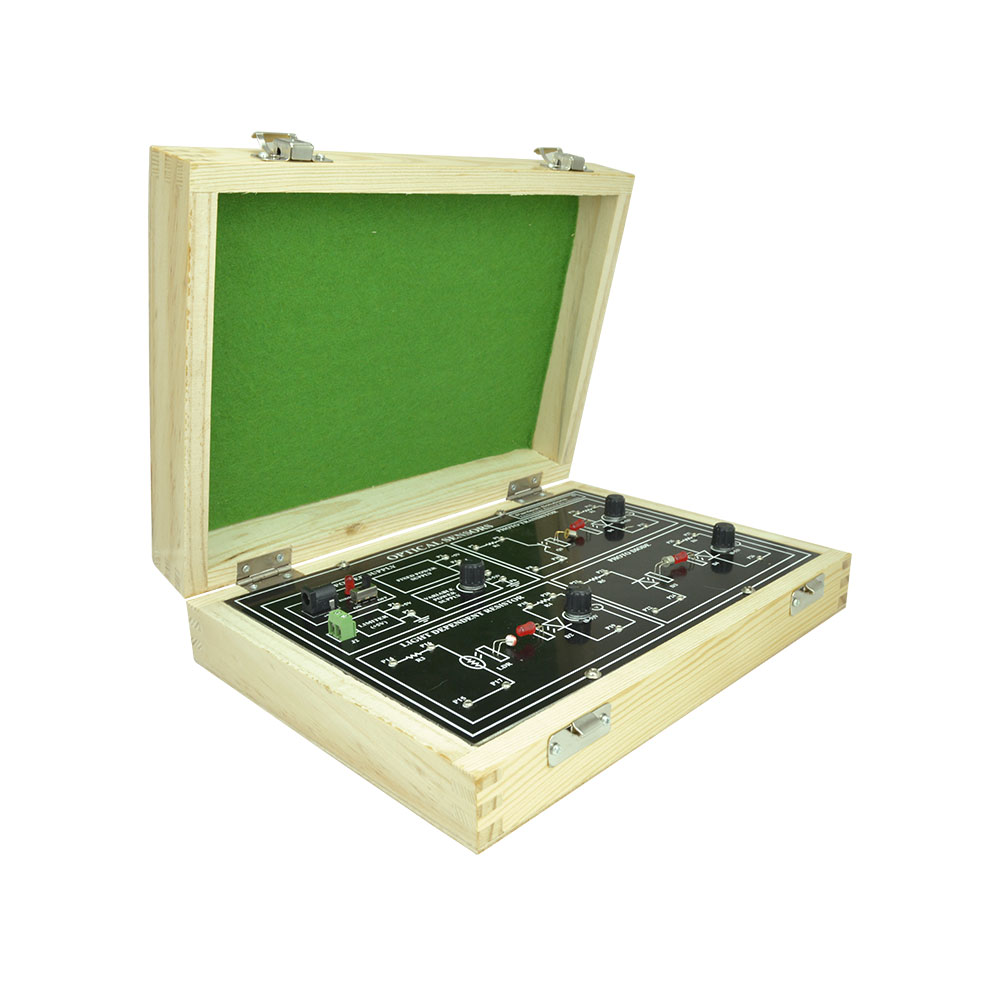
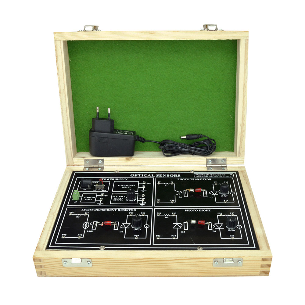
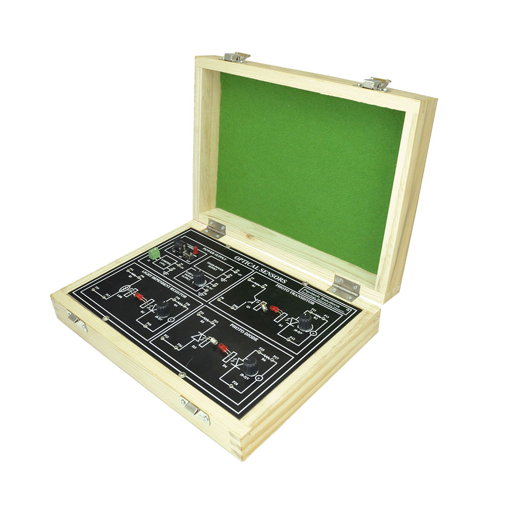
Optical Sensors
- Call for Price
-

-

-
-

-
-
-
- Out of StockRead more

- Fiber optics
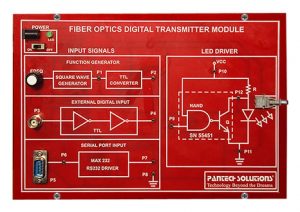
Fiber Optics Digital Transmitter
- Call for Price
-

-
-
- Out of StockRead more

- Fiber optics
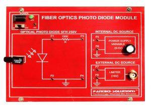
Characteristics of Photo Diode Module
- Call for Price
-

-

Reviews
There are no reviews yet.