Bending Loss Measurement in Fiber Optic System
Aim
To Study the Bending Loss Measurement in Fiber Optic System
Apparatus Required
☞ Fiber Optics Analog Transmitter Module – 01
☞Fiber Optics Analog Receiver Module – 01
☞Plastic Fiber cable 1 meter – 01
☞CRO – 01
☞Adapter +15V/ DC – 02
☞Patch Chords – 06
Theory
Bending Loss
In Fiber Optic System face some losses in communication, which losses accrued from material, cable length, cable bend, couple the more no of fiber optic cable, splicing the fiber cable etc., in bending loss, cable bend will act as a loss in that Fiber Optic System. In Fiber Optic System light signal passes through fiber cable from one end to another end. If bends the fiber cable, the light signal was strike in there both ways. So now only bending loss accrued in the Fiber Optic System.
Optical fiber
The transmission medium in fiber-optic communications systems is an optical fiber. The optical fiber is the transparent flexible filament that guides light from a transmitter to a receiver. An optical information signal entered at the transmitter end of a fiber – optic communications system is delivered to the receiver end by the optical fiber.
Model Diagram for Plastic Fiber cable
This is multi mode plastic fiber cable, in this fiber cable core diameter 1000 micron and fiber cladding index 1.402.
Procedure
☞Connect +15V adapter to both transmitter and receiver module
☞Switch (sw1) ON the transmitter Module, CRO and receiver module (sw1).
☞Set the sine wave output (Vin) 1 Vpp/ 1 KHz at P1.
☞Connect P1 and P8, P9 and P10 using patch chord.
☞Connect the 1 m Plastic fiber cable between transmitter module LED to receiver module Photo Diode.
☞Connect P2 and P4, P5 and P6 using patch chord.
☞Keep Amplifier pot meter in maximum position.
☞Note down the analog output (Vo) on test point P7.
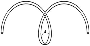
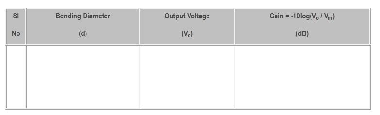
☞Now bend the fiber cable like fig 1, measure the bending diameter and output voltage (Vo), change the bending diameter and tabulate the readings.
Tabular column
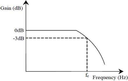
Model Graph