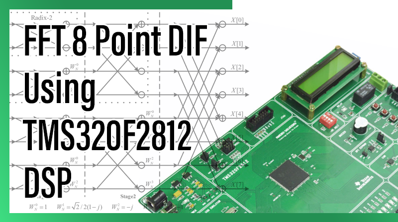
FFT 8 Point DIF Using TMS320F2812 DSP
Aim
To perform the 8 point FFT using DIF process from a given discrete sequence in TMS320F2812 KIT.
Requirements
☞CCS v3.3
☞USB Cable
☞5V Adapter
Theory
A Fast Fourier transform (FFT) is an efficient algorithm to compute the discrete Fourier transform (DFT) and its inverse. There are many distinct FFT algorithms involving a wide range of mathematics, from simple complex number arithmetic to group theory and number theory.
A DFT decomposes a sequence of values into components of different frequencies. This operation is useful in many fields (see discrete Fourier transform for properties and applications of the transform) but computing it directly from the definition is often too slow to be practical. An FFT is a way to compute the same result more quickly: computing a DFT of N points in the naive way, using the definition, takes O(N2) arithmetical operations, while an FFT can compute the same result in only O(N log N) operations. The difference in speed can be substantial, especially for long data sets where N may be in the thousands or millions—in practice, the computation time can be reduced by several orders of magnitude in such cases, and the improvement is roughly proportional to N / log(N). This huge improvement made many DFT based algorithms practical; FFTs are of great importance to a wide variety of applications, from digital signal processing and solving partial differential equations to algorithms for quick multiplication of large integers.
The most well known FFT algorithms depend upon the factorization of N, but there are FFTs with O(N log N) complexity for all N, even for prime N. Many FFT algorithms only depend on the fact that  is an th primitive root of unity, and thus can be applied to analogous transforms over any finitue field, such as number theoretic transforms. Since the inverse DFT is the same as the DFT, but with the opposite sign in the exponent and a 1/N factor, any FFT algorithm can easily be adapted for it.
Procedure for build a project on FFT 8 Point DIF Using TMS320F2812 DSP
Note: Once you install the Code Composer Studio v 3.3 software, the two icons will display in desktop
☞Setup Code Composer Studio v3.3
☞Code Composer Studio
1. Open Setup Code Composer Studio v3.3.
2. In System Configuration, select the board then → Remove all → yes.
☞In family, select C28xx.
☞In platform, select xds100 usb emulator.
☞In Endianness, select little.
☞Select F2812 XDS100 USB Emulator → add → save & quit → no.
Note: The above two steps only for first time to setup the processor in CCS.
3. Open Code Composer Studio v3.3.
4. Project → New.
☞ Project name : type the project name.
☞ Location : Browse, select the project location .
☞ Project Type : Executable(.out)
☞ Target : TMS320C28XX. → Finish.
5. File → New → Source file.
☞Type the program in untitled window.
6. File → Save.
☞Browse our project location then type our project name.c ( .c extension is must) → save.
7. Paste the following two cmd files in our project folder.
☞F2812_EzDSP_RAM_lnk.cmd
☞DSP281x_Headers_nonBIOS.cmd
☞DSP281x_GlobalVariableDefs.c
8. Project → Add files to project.
☞ In file of type : All files
☞Ctrl + Select the following files – projectname.c – DSP281x_GlobalVariableDefs.c – F2812_EzDSP_RAM_lnk.cmd – DSP281x_Headers_nonBIOS.cmd → open.
9. Project → Build Option.
In compiler tab, select Preprocessor
☞Include search path(-i) : C:\tidcs\c28\DSP281x\v120\DSP281x_headers\include
In linker tab, select libraries
☞Search path(-i) : C:\CCStudio_v3.3\C2000\cgtools\lib
☞ Incl libraries(-l) : rts2800_ml.lib.
In linker tab, select Basic
☞Stack Size(-stack) : 0x400 → ok.
10. Project → Build (or) Rebuild all.
11. Connections for TMS320F2812 KIT
☞Connect 5v adpter to TMS320F2812 KIT
☞Connect usb cable to TMS320F2812 KIT from pc.
☞Power on the TMS320F2812 KIT.
12. Debug → connect.
13. File → Load Program → Browse and select the projectname.out file → open
14. Debug → Go main.
15. View → memory
Enter An Address : 0x3F9200 → Enter.
Type the input.
For example
0x3F9200 – 0x0001
0x3F9201 – 0x0002
0x3F9202 – 0x0003
0x3F9203 – 0x0004
0x3F9204 – 0x0004
0x3F9205 – 0x0003
0x3F9206 – 0x0002
0x3F9207 – 0x0001
16. View → Watch window → watch1.
Type the following array variable.
☞tr( real part output)
☞ti( imaginary part output)
17. Debug → Run.
18. Debug → Halt
19. See the output at following location, View → memory
Enter An Address : 0x3F9210 → Enter.(real part output)
For example
0x3F9210 – 0x0014
0x3F9111 – 0xFFFB (-5)
0x3F9112 – 0x0000
0x3F9113 – 0x0000
0x3F9210 – 0x0000
0x3F9210 – 0x0000
0x3F9210 – 0x0000
0x3F9210 – 0xFFFB (-5)
20. View → memory
Enter An Address: 0x3F9220 → Enter.(imaginary part output)
For example
0x3F9220 – 0x0000
0x3F9121 – 0xFFFE (-2)
0x3F9122 – 0x0000
0x3F9123 – 0x0000
0x3F9220 – 0x0000
0x3F9220 – 0x0000
0x3F9220 – 0x0000
0x3F9220 – 0x0002
21. Or see the ouput at watch window.
Note: watch window will show exact decimal values, processor memory location will show a hexadecimal values.
Program for FFT 8 Point DIF Using TMS320F2812 DSP
#include "DSP281x_Device.h"
#include
#define PI      3.14159
void InitSystem();
float x[8],tr[8],ti[8],s1r[8],s1i[8],s2r[8],s2i[8],Xr[8],Xi[8],Yr[8],Yi[8];
const float W0r = 1,
W0i = 0,
W1r = 0.707,
W1i = -0.707,
W2r = 0,
W2i = -1,
W3r = -0.707,
W3i = -0.707;
void main()
{
        int *Input,*Real_out,*Imag_out;
        int i=0;
        Input = (int *)0x003F9200;
        Real_out = (int *)0x003F9210;
        Imag_out = (int *)0x003F9220;
        InitSystem();
        for(i=0;i<8;i++)
        {
                        x[i] = 0;
                        x[i] = *(Input + i);
        }
// stage one process
        s1r[0] = (int)(x[0] + x[4]);
        s1i[0] = 0;
        s1r[1] = (int)(x[1] + x[5]);
        s1i[1] = 0;
        s1r[2] = (int)(x[2] + x[6]);
        s1i[2] = 0;
        s1r[3] = (int)(x[3] + x[7]);
        s1i[3] = 0;
        s1r[4] = (int)(x[0] - x[4]) * W0r;
        s1i[4] = 0;
        s1r[5] = (int)(x[1] - x[5]) * W1r;
        s1i[5] = (int)(x[1] - x[5]) * W1i;
        s1r[6] = 0;
        s1i[6] = (int)(x[2] - x[6]) * W2i;
        s1r[7] = (int)(x[3] - x[7]) * W3r;
        s1i[7] = (int)(x[3] - x[7]) * W3i;
// stage two process
        s2r[0] = (s1r[0] + s1r[2]);
        s2i[0] = (s1i[0] + s1i[2]);
        s2r[1] = (s1r[1] + s1r[3]);
        s2i[1] = (s1i[1] + s1i[3]);
        s2r[2] = (s1r[0] - s1r[2]) * W0r;
        s2i[2] = 0; // (s1i[0] - s1i[2]) * W0i;
        s2r[3] = 0; // (s1r[1] - s1r[3]) * W2r;
        s2i[3] = (s1r[1] - s1r[3]) * W2i;
        s2r[4] = (s1r[4] + s1r[6]);
        s2i[4] = (s1i[4] + s1i[6]);
        s2r[5] = (s1r[5] + s1r[7]);
        s2i[5] = (s1i[5] + s1i[7]);
        s2r[6] = (s1r[4] - s1r[6]) * 1;
        s2i[6] = (s1i[4] - s1i[6]) * 1;
        Yr[0] = s1r[5] - s1r[7];
        Yi[0] = s1i[5] - s1i[7];
        Yr[1] = ((Yr[0] * W2r) - (Yi[0] * W2i));
        Yi[1] = ((Yr[0] * W2i) + (Yi[0] * W2r));
        s2r[7] = Yr[1];
        s2i[7] = Yi[1];
//  output
        Xr[0] = (s2r[0] + s2r[1]);
        Xi[0] = (s2i[0] + s2i[1]);
        Xr[1] = (s2r[0] - s2r[1]);
        Xi[1] = (s2i[0] - s2i[1]);
        Xr[2] = (s2r[2] + s2r[3]);
        Xi[2] = (s2i[2] + s2i[3]);
        Xr[3] = (s2r[2] - s2r[3]);
        Xi[3] = (s2i[2] - s2i[3]);
        Xr[4] = (s2r[4] + s2r[5]);
        Xi[4] = (s2i[4] + s2i[5]);
        Xr[5] = (s2r[4] - s2r[5]);
        Xi[5] = (s2i[4] - s2i[5]);
        Xr[6] = (s2r[6] + s2r[7]);
        Xi[6] = (s2i[6] + s2i[7]);
        Xr[7] = (s2r[6] - s2r[7]);
        Xi[7] = (s2i[6] - s2i[7]);
// bit reversal
        tr[0] = Xr[0];
        ti[0] = Xi[0];
        tr[1] = Xr[4];
        ti[1] = Xi[4];
        tr[2] = Xr[2];
        ti[2] = Xi[2];
        tr[3] = Xr[6];
        ti[3] = Xi[6];
        tr[4] = Xr[1];
        ti[4] = Xi[1];
        tr[5] = Xr[5];
        ti[5] = Xi[5];
        tr[6] = Xr[3];
        ti[6] = Xi[3];
        tr[7] = Xr[7];
        ti[7] = Xi[7];
// sending output array to memory location
        for(i=0;i<8;i++)
        {
                *Real_out ++= tr[i];
                *Imag_out ++= ti[i];
        }

        for(;;);
}


void InitSystem()
{
                EALLOW;
                SysCtrlRegs.WDCR= 0x0068;            // Setup the watchdog                                                                      //0x0068  to disable the Watchdog , Prescaler = 1                                                                    // 0x00AF  to NOT disable the Watchdog, Prescaler = 64
              SysCtrlRegs.SCSR = 0;                  // Watchdog generates a RESET
              SysCtrlRegs.PLLCR.bit.DIV = 10;        // Setup the Clock PLL to multiply by 5
              SysCtrlRegs.HISPCP.all = 0x1; // Setup Highspeed Clock Prescaler to divide by 2
              SysCtrlRegs.LOSPCP.all = 0x2; // Setup Lowspeed CLock Prescaler to divide by 4
              // Peripheral clock enables set for the selected peripherals.
              SysCtrlRegs.PCLKCR.bit.EVAENCLK=0;
              SysCtrlRegs.PCLKCR.bit.EVBENCLK=0;
              SysCtrlRegs.PCLKCR.bit.SCIAENCLK=0;
              SysCtrlRegs.PCLKCR.bit.SCIBENCLK=0;
              SysCtrlRegs.PCLKCR.bit.MCBSPENCLK=0;
              SysCtrlRegs.PCLKCR.bit.SPIENCLK=0;
              SysCtrlRegs.PCLKCR.bit.ECANENCLK=0;
              SysCtrlRegs.PCLKCR.bit.ADCENCLK=0;
              EDIS;

}
Result
Thus, the 8 point FFT of given discrete sequence has performed and the result is stored at memory location(0x3F9210 & 0x3F9220).