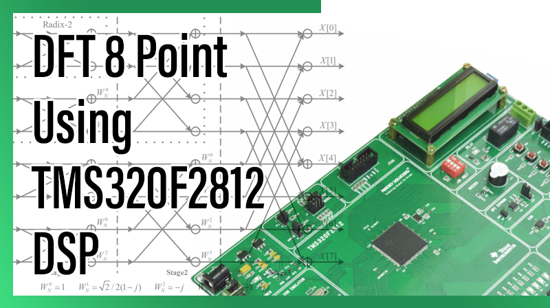
DFT 8 Point Using TMS320F2812 DSP
Aim
To perform the 8 point DFT process from a given discrete sequence in TMS320F2812 KIT.
Requirements
- CCS v3.3
- TMS320F2812 KIT
- USB Cable
- 5V Adapter
Theory
The sequence of N complex numbers x0, …, xN−1 is transformed into another sequence of N complex numbers according to the DFT formula
It transforms one function into another, which is called the frequency domain representation, or simply the DFT, of the original function (which is often a function in the time domain).
The DFT requires an input function that is discrete. Such inputs are often created by sampling a continuous function, such as a person’s voice. The discrete input function must also have a limited (finite) duration, such as one period of a periodic sequence or a windowed segment of a longer sequence. Unlike the discrete time Fourier transform (DTFT), the DFT only evaluates enough frequency components to reconstruct the finite segment that was analyzed. The inverse DFT cannot reproduce the entire time domain, unless the input happens to be periodic. Therefore it is often said that the DFT is a transform for Fourier analysis of finite-domain discrete-time functions.
Procedure for build a project on DFT 8 Point Using TMS320F2812 DSP
Note: Once you install the Code Composer Studio v 3.3 software, the two icons will display in desktop
- Setup Code Composer Studio v3.3
- Code Composer Studio
1. Open Setup Code Composer Studio v3.3.
2. In System Configuration, select the board then → Remove all → yes.
- In family, select C28xx.
- In platform, select xds100 usb emulator.
- In Endianness, select little.
- Select F2812 XDS100 USB Emulator → add → save & quit → no.
Note: The above two steps only for first time to setup the processor in CCS.
3. Open Code Composer Studio v3.3.
4. Project → New.
- Project name: type the project name.
- Location: Browse, select the project location .
- Project Type: Executable(.out)
- Target: TMS320C28XX. → Finish.
5. File → New → Source file.
- Type the program in untitled window.
6. File → Save.
- Browse our project location then type our project name.c ( .c extension is must) → save.
7. Paste the following two cmd files in our project folder.
- F2812_EzDSP_RAM_lnk.cmd
- DSP281x_Headers_nonBIOS.cmd
- DSP281x_GlobalVariableDefs.c
Project → Add files to project.
- In file of type : All files
- Ctrl + Select the following files – projectname.c – DSP281x_GlobalVariableDefs.c – F2812_EzDSP_RAM_lnk.cmd – DSP281x_Headers_nonBIOS.cmd open.
9. Project → Build Option.
In compiler tab, select Preprocessor
- Include search path(-i) : C:\tidcs\c28\DSP281x\v120\DSP281x_headers\include
In linker tab, select libraries
- Search path(-i) : C:\CCStudio_v3.3\C2000\cgtools\lib
- Incl libraries(-l) : rts2800_ml.lib.
In linker tab, select Basic
- Stack Size(-stack): 0x400 → ok.
10. Project → Build (or) Rebuild all.
11. Connections for TMS320F2812 KIT
- Connect 5v adpter to TMS320F2812 KIT.
- Connect usb cable to TMS320F2812 KIT from pc.
- Power on the TMS320F2812 KIT.
12. Debug → connect.
13. File → Load Program → Browse and select the projectname.out file → open
14. Debug → Go main.
15. View → memory
Enter An Address : 0x3F9100 → Enter.
Type the input.
For example:
0x3F9100 – 0x0001
0x3F9101 – 0x0001
0x3F9102 – 0x0001
0x3F9103 – 0x0000
0x3F9104 – 0x0000
0x3F9105 – 0x0000
0x3F9106 – 0x0000
0x3F9107 – 0x0000
16. Debug → Run.
17. Debug → Halt.
18. See the output at following location, View → memory
Enter An Address:0x3F9110 → Enter.(REAL PART)
For example
0x3F9110 – 0x0003
0x3F9111 – 0x0001
0x3F9112 – 0x0000
0x3F9113 – 0x0000
0x3F9114 – 0x0001
0x3F9115 – 0x0000
0x3F9116 – 0xFFFF
0x3F9117 – 0x0000
19. View → memory
Enter An Address : 0x3F9120 → Enter.(IMAGINARY PART)
For example
0x3F9120 – 0x0000
0x3F9121 – 0xFFFF
0x3F9122 – 0xFFFF
0x3F9123 – 0x0001
0x3F9124 – 0x0000
0x3F9125 – 0xFFFF
0x3F9126 – 0x0000
0x3F9127 – 0x0001
Program for DFT 8 Point Using TMS320F2812 DSP
#include "DSP281x_Device.h"
#include
#define   PI     3.14159
#define N       8
void InitSystem();
void main()
{
        int *Input,*Real_out,*Imag_out;
        int i=0,j=0,k=0,real_temp=0,imag_temp=0;
        double teta=0,Real_coeff[64],Imag_coeff[64];
        int n=0,b=0,c=0;
        Input = (int *)0x003F9100;
        Real_out = (int *)0x003F9110;
        Imag_out = (int *)0x003F9120;
        InitSystem();
        for(c=0;c<8;c++)
        {
                for(n=0;n<8;n++)
                {
                        teta = ((2 * PI * n * c) / N);         //  c = k in formulae
                        Real_coeff[b] = cos(teta);
                        Imag_coeff[b] = -sin(teta);
                        b++;
                }
        }

        for(i=0;i<8;i++)
        {
                real_temp=0;
                imag_temp=0;
                for(j=0;j<8;j++)
                {
                        real_temp += (Input[j] * Real_coeff[k]);
                        imag_temp += (Input[j] * Imag_coeff[k]);
                        k++;
                }
                *(Real_out + i) = real_temp;
                *(Imag_out + i) = imag_temp;

        }

        while(1);
}


void InitSystem()
{
                EALLOW;
                SysCtrlRegs.WDCR= 0x0068;            // Setup the watchdog
                                             // 0x0068  to disable the Watchdog , Prescaler = 1                                                                        // 0x00AF  to NOT disable the Watchdog, Prescaler = 64
                SysCtrlRegs.SCSR = 0;                  // Watchdog generates a RESET
                SysCtrlRegs.PLLCR.bit.DIV = 10;        // Setup the Clock PLL to multiply by 5
                SysCtrlRegs.HISPCP.all = 0x1; // Setup Highspeed Clock Prescaler to divide by 2
                SysCtrlRegs.LOSPCP.all = 0x2; // Setup Lowspeed CLock Prescaler to divide by 4
                // Peripheral clock enables set for the selected peripherals.
                SysCtrlRegs.PCLKCR.bit.EVAENCLK=0;
                SysCtrlRegs.PCLKCR.bit.EVBENCLK=0;
                SysCtrlRegs.PCLKCR.bit.SCIAENCLK=0;
                SysCtrlRegs.PCLKCR.bit.SCIBENCLK=0;
                SysCtrlRegs.PCLKCR.bit.MCBSPENCLK=0;
                SysCtrlRegs.PCLKCR.bit.SPIENCLK=0;
                SysCtrlRegs.PCLKCR.bit.ECANENCLK=0;
                SysCtrlRegs.PCLKCR.bit.ADCENCLK=0;
                EDIS;
}
Result
Thus, the 8 point DFT process from a given discrete sequence has performed and the result is stored at memory location(0x3F9110 & 0x3F9120)..