

Controlling LED with your Brain Attention using Brainwave Starter kit and Arduino platform
Call for Price
This step-by-step guide is intended to quickly get a typical Arduino board user up and running with the MindWave Mobile. This guide will show how to setup the HC-05 Bluetooth Module quickly for communication with the MindWave Mobile and gives example code to parse the output stream. The parsed output stream can then be used to perform various tasks such as to control the speed of a motor, to light up LEDs, and to control the position of a servo motor, etc.
Description
Features
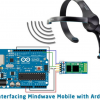
☞Interfacing the Mindwave Mobile Device with an Arduino board using HC-05 Bluetooth module
☞Acquiring the Attention eSense values from the data stream.
☞LED controlled by Attention level of mindwaves.
☞Display the attention levels in serial monitor.
Introduction
This step-by-step guide is intended to quickly get a typical Arduino board user up and running with the Mindwave Mobile. This guide will show how to setup the HC-05 Bluetooth module quickly for communication with the Mindwave Mobile and gives example code to parse the output stream. The parsed output stream can then be used to perform various tasks such as to control the speed of a motor, to light up LEDs, and to control the position of a servo motor, etc.
Demonstration Video
Required Materials
This application requires the following materials
Hardware’s:
☞Arduino Board
☞USB cable (for Arduino)
☞Connecting Wires.
☞Bluetooth dongle, if your computer does not have internal bluetooth capabilities
Software’s
☞Arduino 1.0.5-r2
Project Materials

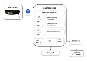
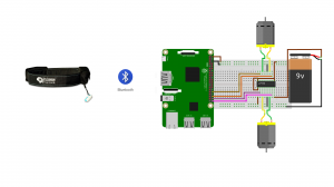
Connection Diagram

Note: Keep the Rx (Pin1) line in Open connection
Steps to follow [Output at LED and Serial Monitor]
☞. Switch ON the Mindwave Mobile and unpaired the last connections, then OFF the Mindwave Device.
☞. Program (Upload the sketch) the “Mindwave_Arduino_Attention_LED_UART” source code to Arduino Board using Arduino compiler.
☞. Open the “Serial Monitor” in Arduino compiler with 57600 baudrate.
☞. Make all the connection as per the connection diagram, and then switch ON the Arduino Board.
☞. After the 7 Seconds when arduino board was ON, switch ON the Mindwave Device.
☞. Now the Mindwave Device and Arduino Board will pair automatically.
☞. Wear the Mindwave Device in Head, and give the attention.
☞. Check the LED (D13) variation with respect your attention level.
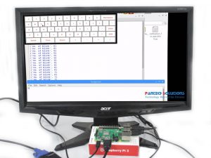
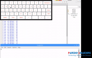
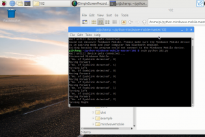
☞. And also see the Serial Monitor to know your attention levels.
Steps to follow [Output at LED only]
☞. Switch ON the Mindwave Mobile and unpaired the last connections, then OFF theMindwave Device.
☞. Program (Upload the sketch) the “Mindwave_Arduino_Attention_LED” source code to Arduino Board using Arduino compiler.
☞. Make all the connection as per the connection diagram, and then switch ON the Arduino Board.
☞. After the 7 Seconds when arduino board was ON, switch ON the Mindwave Device.
☞. Now the Mindwave Device and Arduino Board will pair automatically.
☞. Wear the Mindwave Device in Head, and give the attention.
☞. Check the LED (D13) variation with respect your attention level.
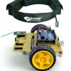
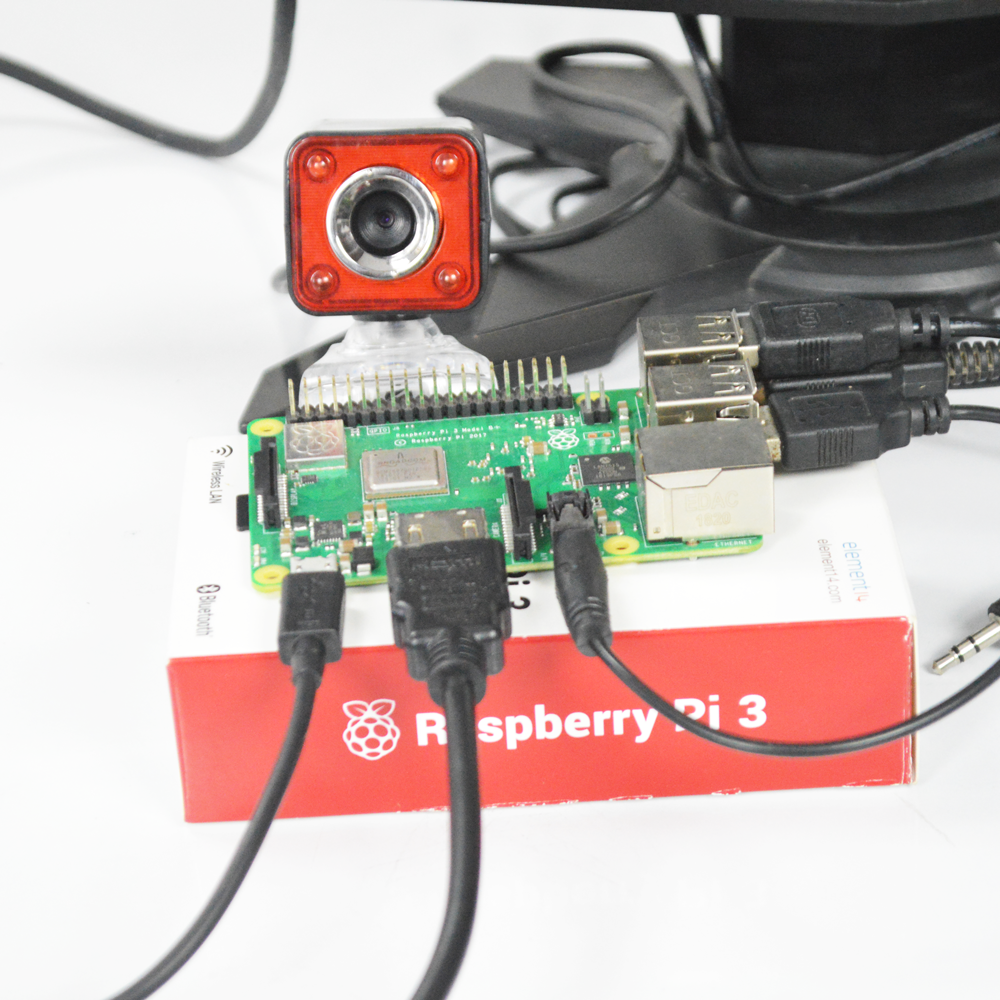
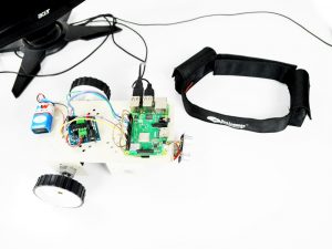
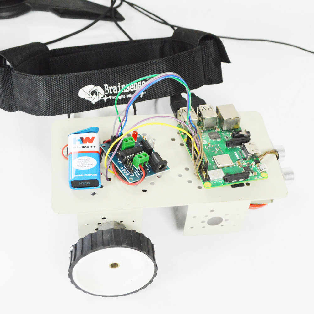
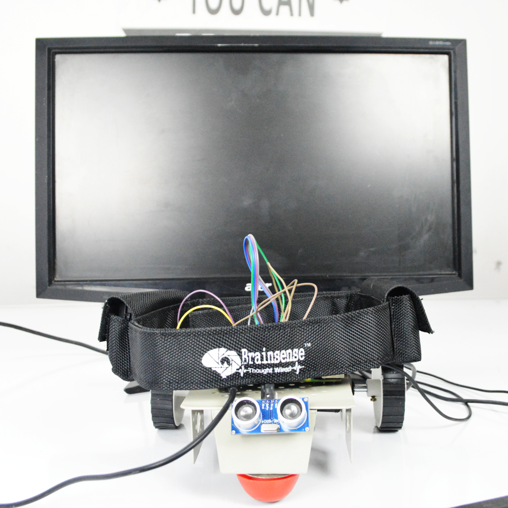
Real View of Arduino with Mindwave mobile

Some Tips about Project
☞. The Indication LED of Mindwave Device glow continuously in blue color, when it’s paired with arduino HC-05 module.
☞. If blue LED in blinking conditions means, it’s not pair with device.
☞. The Mindwave Mobile and HC-05 module automatically paired, when we switch ON the both device.
☞. Before sketch the program, you have to disconnect the Tx and Rx lines (Keep in Open connection).
Output Details
The LED (D13) becomes ON, when you give High attention. It’s become OFF, when you give next High attention, like that every High attention you can change the state of LED.
Upload the sketch to Arduino board

Serial Monitor Output

Program for Mindwave_Arduino_Attention_LED_UART
Title: Mindwave_Arduino_Attention_LED_UART
//                                                           //
//                                                         //
//    Program       : Brainsense with Arduino              //
//    Interfacing   : HC-05 Bluetooth module               //
//    Output        : LED Control using Attention          //

#define BAUDRATE 57600
#define LED 13

byte payloadData[32] = {0};
byte Attention[5]={0};
byte checksum=0;
byte generatedchecksum=0;
int  Plength,Temp;
int  Att_Avg=0,On_Flag=1,Off_Flag=0;
int  k=0;
signed int  j=0;


void setup()
{
  Serial.begin(BAUDRATE);           // USB
  pinMode(LED, OUTPUT);
}

byte ReadOneByte()           // One Byte Read Function
{
  int ByteRead;
  while(!Serial.available());
  ByteRead = Serial.read();
  return ByteRead;
}

void loop()                     // Main Function
{
  while (1)
  {
    if(ReadOneByte() == 170)        // AA 1 st Sync data
    {
      if(ReadOneByte() == 170)      // AA 2 st Sync data
      {
        Plength = ReadOneByte();
        if(Plength == 32)   // Big Packet
        {
          generatedchecksum = 0;
          for(int i = 0; i < Plength; i++)
          {
            payloadData[i]     = ReadOneByte();      //Read payload into memory
            generatedchecksum  += payloadData[i] ;
          }
          generatedchecksum = 255 - generatedchecksum;
          checksum  = ReadOneByte();

          if(checksum == generatedchecksum)        // Varify Checksum
          {
            if (payloadData[28]==4)
            {
              if (j<4)
               {
                 Attention [k] = payloadData[29];
                 Temp += Attention [k];
                 j++;
               }
               else
               {
                 Att_Avg = Temp/4;

                 if (Att_Avg>80)
                 {
                   if(On_Flag==1)
                   {
                     digitalWrite(LED, HIGH);
                     On_Flag=0;
                     Off_Flag=1;
                   }
                   else if(Off_Flag==1)
                   {
                     digitalWrite(LED, LOW);
                     On_Flag=1;
                     Off_Flag=0;
                   }
                 }
                 j=0;
                 Temp=0;
               }
            }
           }
         }
       }
     }
   }
}
Reference Documents Links
Interfacing Mindwave Mobile with Arduino
Reference Video Links
Interfacing Mindwave Mobile with Arduino
Additional information
| Weight | 0.100000 kg |
|---|
Related products
-
-
Sale!
Add to cart
- Brain computer Interface projects
Brain Actuated Applications for Paralyzed people
- ₹30,000.00 Exc Tax
-
-
Sale!

Reviews
There are no reviews yet.