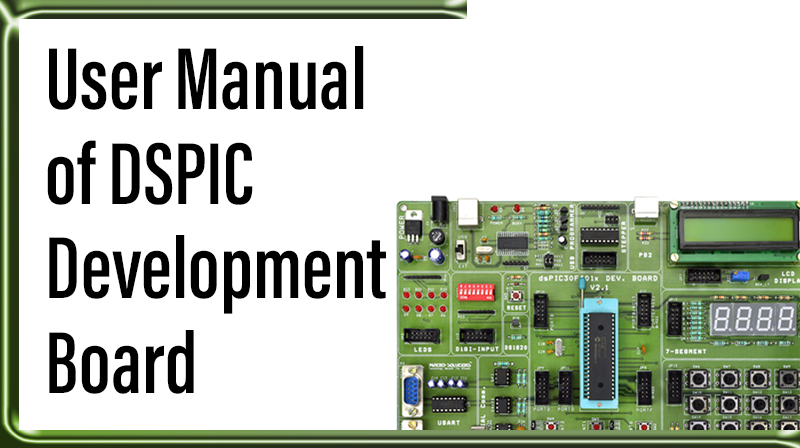
User Manual of DSPIC Development Board
The DSPIC DEVELOPMENT BOARD has the following hardware features:
☞40-pin ZIF socket.
☞+5V regulator for direct input from 9V, 500 mA AC/DC wall adapter
☞Two no’s RS-232 socket and associated hardware for RS-232 interface.
☞ICSP USB 2.0 Programmer with busy LED indication
☞Two 5 KΩ pot and one LM35 for devices with analog inputs.
☞Four push button switches for external interrupts and Reset.
☞Red power-on indicator LED.
☞Eight red LEDs connected to 10 Pin FRC.
☞A 10 MHz crystal oscillator.
☞Microchip 25C040 Serial SPI EEPROM.
☞Atmel AT24c04 Serial I2C EEPROM
☞Dallas DS1307 Serial I2C Real-time Clock
☞LCD display with backlight Selection Jumper.
☞Piezo buzzer
☞Dallas DS1820 thermal sensor.
☞Four 7Segment multiplexed display
☞ULN2803 driver for unipolar Stepper motors
☞4×4 matrix keypad
☞8 way DIP switch for digital input
☞10-way Configuration DIP switch for multiple operation
DSPIC DEVELOPMENT HARDWARE

SAMPLE DEVICES
One FLASH device is included. The device types may change, but will generally include DSPIC30F 40- pin DIP devices.
SAMPLE PROGRAMS
The DSPIC DEVELOPMENT Kit includes a CD-ROM with sample programs. These programs may be used with the included sample devices. For each type of device (DSPIC30F), demo source code with compiled Hex file is provided.
DSPIC DEVELOPMENT BOARD LAYOUT

Hardware Details
SOCKETS
40 Pin ZIF socket is provided for the processor. Microcontroller can be removed from the board easily. This socket is intended to use our development board as programmer to program other IC’s. 10 pin FRC box type connectors: This will be found in each section of DSPIC 30F development board. A 10 pin FRC cable is used to make connection with the main board section. Any 8 bit port of microcontroller can be used for interconnection. Ports having less than 8 bits are used as control signals for various sections.

Pins 1-8 are Data Pins. Pin 9 is VDD and the Pin 10 is GND. All 10 Pin FRC connectors will follow the same rule.
JUMPER SETTINGS

CONFIG SWITCH
SW1: 10 way Multifunctional switch

ANi/P SWITCH
SW24: 4 way analog channel selection switch

POWER SUPPLY
The external power can be AC or DC, with a voltage (15V, 1A output). The DSPIC board produces +5V using an LM7805 voltage regulator, which provides supply to the peripherals. Power supply is controlled through slide switch SW2.

Installation Notes
Installing MPLAB IDE
Open up the user CD comes with DSPIC Microcontroller Board, Navigate to MPLAB IDE Folder
Double Click Setup.exe and Click → Next

Click >>I accept the terms of the license agreement and Click → Next

Select >> Complete check box and Click → Next

Click >> Next

Click >> I accept the terms of the license agreement for both Application Maestro as well as MPLAB c32 windows and Click → Next, Next


Click >> Next to Start Copying Files

Now the MPLAB IDE setup will Progress

After finishing installation MPLAB IDE, it will prompt for HI-TECH C Installation. Click → No
Click >> Finish to InstallShield Wizard Complete

Just Close the MPLAB IDE Document Support

Installing MPLAB C30 compiler
Purchase this compiler from microchip or download their 60 days student version. Install the compiler as per their manual. Then follow the next step.
Creating a Project on MPLAB IDE
Double Click the MPLAB IDE v8.xx from desktop

To create a new project, Click → Project and Project Wizard.

At the first page of Project Wizard, Click >> Next.

Step ONE: Next, you will need to select the device for your project. For this demonstration I will use DSPIC16F877A as the device.

Afterselecting the device, click >> Next

Step TWO: Select the Compiler for your Project.

Click the Active Toolsuite drop box and select MPLAB C30 ToolSuite.

There should not be any red “X” mark (For those with the red “X”, please reinstall the MPLAB C30). Click Next to continue.
Example: See the “Red X” mark that appears before CCS C compilers

Step Three: Select the directory to store your project and your project name.
i. Click on Browse to open a browser where you choose the directory and the project name.
ii. It is advised that you use a new folder for a new project, and all the coding file (c file, h file, asm file) should be stored under the same folder.

Now enter the Project Name and Click >> Save

Click >> Next to the following window

Step four, If you have an existing file Select that file and Click Add>>, Otherwise Just Skip this step by clicking Next.

You have successfully created the project. Click Finish to continue.

The project that you create will be open after you successfully created it, and this is what you will see at the IDE, a Project window and an Output window.
If you don’t have these windows on your IDE, you can always enable it back by clicking View >> Project and View >> Output.

Click on the icon (New File) to create a new file.

Enter All your codes or Enter spacebar once and Click File >> Save.

Enter the file name with “.c” extension. Check the box “Add File To Project”. Click Save to save it in project directory.

IF you forget to Check the box “Add File To Project”, You can add your source file by right clicking at the Source File and click Add Files.

Select the file that is being saved. Click Open

Now the code file “.c” is added to your project. You can see that it is shown under the Source Files at the Project window.

Now Right Click On Linker Script and Click Add Files…

Navigate to “C:\Program Files\Microchip\MPLAB C30\support\dsPIC30F\gld” and select your IC’s linker script. Click Open

Now everything has been done. Now write your code or modify the existing code….

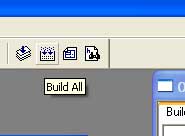
Click build All to compile the project and correct the error, do rebuild etc…
Configuring Programmer for DSPIC Development Board
First attach the DSPIC Microcontroller Development Board with PC via USB cable.
Connect the 9V AC/DC Adapter with Development Board or Just use USB power.
Turn ON the Power Switch (either USB side or EXT side).
Wait until the PICkit2 Finishes Driver Installation*. If the driver not detected just try to reconnect or RESTART your system, then try again.

After Finishing the Hardware driver installation. Open MPLAB IDE. Select Programmer >> Select Programmer >> PICkit2

Note*: Driver installation is required for this board when it is connected to the PC for the very first time.
If the Kit is properly connected, you can see the PICkit2 Icon set on the Toolbar (Yellow Set) and the PICkit2 Ready Message. Very First icon is used for “Programming the device”.

Finally open our Example Programs, Burn it to the controller, do the hardware connection as per Chapter 4 and See the result.
POSSIBLE ERRORS
Error 1: MPLAB may throw “Write Failure-Get lost Error”. If it does, follow the instructions below,
☞a) Unplug the Power supply from target board
☞b) Close MPLAB
☞c) Plug the AC/DC adapter
☞d) Reopen MPLAB
Error 2: MPLAB may throw “target not found” error or “Unspecified device error”. If it does, follow the instructions below
☞a) Ensure whether the DSPIC microcontroller placed properly in ZIF jacket.
☞b) In Configure–>Select device, ensure DSPIC16F877A (or any) is selected.
Error 3: MPLAB may throw “Verified Failed” error, due to the following
☞a) Hex File may be old, so compile the project once and try Programming.
☞b) Faulty microcontroller device, Replace it with new one.
Note *: If the error still retains check your windows firewall or antivirus software to allow this MPLAB and DsPICkit2 programmer.
Example Programs and Connections
SEVEN SEGMENT

I2C EEPROM

ADC

DIGITAL INPUTS

DS1307

DS1820

INTERRUPT

PS2

KEYPAD

LCD

LED

BUZZER

SPI EEPROM

STEPPER MOTOR

USART1

USART2

Setting up HyperTerminal
HyperTerminal is automatically installed under Programs → Accessories,
Click Start >> Programs >> Accessories >> Communications >> HyperTerminal
Enter Name (e.g. Com1_9600) and choose any one ICON.

Click the drop-down arrow by Connect Using >> COM1 >> Click OK

COM1 Properties, Port Settings

☞Bits per Second: select 9600 (or desired baud rate)
☞Data Bits: select 8
☞Parity: select None
☞Stop Bits: select 1
☞Flow Control: select none
☞Click OK
Now you get the HyperTerminal window.