User manual for PIC Evaluation Board
Introduction
The PIC Evaluation Board can be used stand-alone board built with an in-circuit serial programmer. Sample programs are provided to demonstrate the unique features of the supported devices.
The PIC Evaluation Board Kit comes with the following:
- PIC Evaluation Board
- Sample devices (16F877A)
- Programmer Cable, Serial Cable
- CD-ROM, which contains: a) Sample programs b)PIC Evaluation Development Board User ’s Guide
Board Features
PIC Evaluation Board has the following features:
- Supports all 40 pin 16 and 18 series PIC’s compatible with 16F877
- Has on board 5V power supply.
- Serial interface for standard 3 wire serial communication
- 10MHz crystal oscillator
- 32 I/O pins (all except RA4) available on FRC box connectors
- Connector for LCD module including contrast adjust and backlight selection
- ICSP via simple JDM Programmer
- Three Relay Driver
- Single Channel ADC interfacing
- General Purpose Area for Additional components
- External Interrupt via RB0
Hardware:
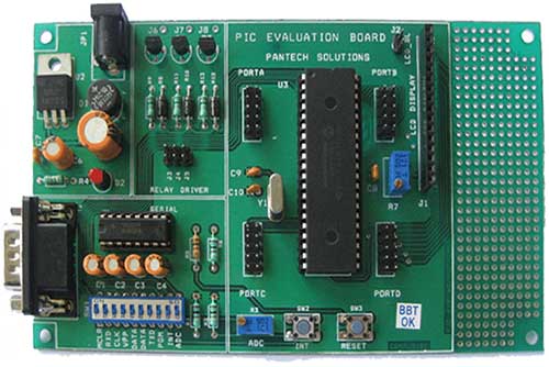
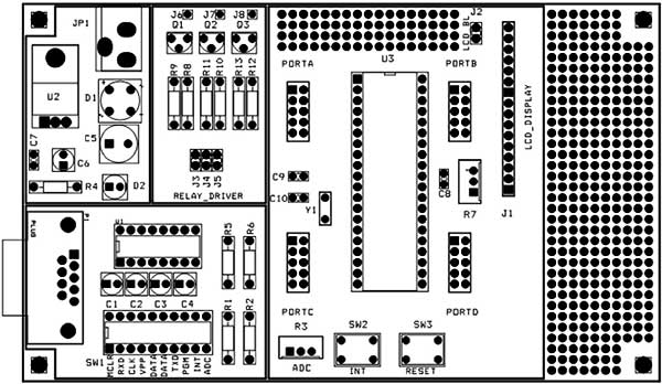
Board Layout:
Jumper Settings:
| JUMPER | SECTION | DESCRIPTION |
| J2 | LCD | Placing a jumper will give the backlight for LCD |
| J3, J4 and J5 | RelayDriver | Put a jumper to connect J3, J4 and J5 with RC0, RC1 and RC2respectively |
| J6, J7 and J8 | RelayDriver | Relay driver outputs and should be connected with relays along with GND |
CONFIG Switch:
SW1: 10 way Multifunctional switch
| DIP SWITCH PIN | DESCRIPTION |
| MCLR | Turn ON this pin for normal run |
| TXD and RXD | RS232 communication transmit, receive pins |
| CLK, VPP, DATA, DATAand PGM | ICSP Pins. Turn ON these pins to burn the program (hex file) into the microcontroller |
| INT | External Interrupt at RB0 |
| ADC | This Pin connects RA0 with POT R3 (ADC) |
In System Programming (ISP):
PIC Evaluation Board has many features; one of the important features is ISP. By Using ISP capability we can program the PIC at the board itself. There is no need to remove the IC for re- programming. The following steps will give you the way to use our On-Board ISP facility.
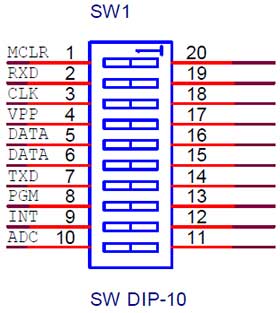
Fig.1 10-Way DIP switch Connection
- Connect ISP Cable provided with the PIC Evaluation Board between DB9 connector on the board and the PC serial port.
- We have given IC-PROG Programmer software with this evaluation kit. Configure the software as necessary. See chapter 2 for how to configure icprog software.
- Connect 9V supply adapter provided with PIC board to the DC socket.
- Turn on the DIP switch pins CLK, VPP, DATA, DATA and PGM and verify all the other pins are in off condition.
- Open Hex in IC-PROG by File >> Open file >> “test. hex”
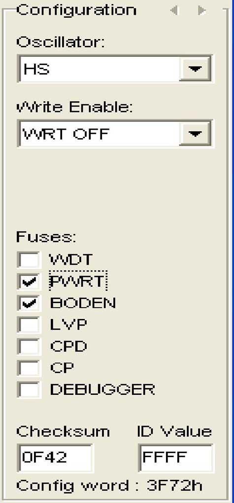
- Select Configuration bits
- Click Program icon in IC-PROG software.
- Wait for “successfully verified” message box.
- Turn ON DIP switch pin MCLR and turn OFF all the remaining pins. Now if you connect LED between GND and port pins, the LED will blink.
Oscillator Selection
Oscillator is necessary to generate clock for the entire Pic-micro unit inside the chip to RUN. There are four types of Oscillators which are subjected to PIC.
- LP Low Power Crystal
- XT Crystal/Resonator
- HS High Speed Crystal/Resonator
- RC Resistor/Capacitor
- Oscillators LP, XT, HS are Crystal type oscillators of varying frequency.
- Oscillators having frequency less than 455 KHz are considered as Low power Oscillators (LP)
- Oscillators having frequency range from 455 KHz to 4 MHz are considered to be XT oscillator.
- Oscillators having frequency range above 4 MHz are considered as High Speed Oscillators (HS).
- A combination of Resistor and Capacitor is known as RC Oscillator So, we need to do the following settings for all of our example programs
RS232 in Asynchronous mode:
Another important Feature is RS232 communication. This feature is very helpful when controlling our PIC from a PC. Here the PIC and PC are connected in asynchronous mode. In asynchronous mode of communication we can send and receive data at the same time. Fig.2 shows the internal structure of the cable connecting Serial Port (Com1, com2, Etc) of your PC and the DB9 connector on the board.
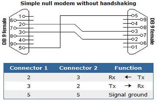
Fig.2 Serial Cable Connection
Most of the PCs are using DB9 male connector for their serial port. PIC Evaluation Board also having the same. So we have provided connector cable having female connector on both ends. This will avoid pin confusions between male and female.
PicMicro and PC are working at different logic levels. PIC is working under TTL logic and your PC is working at RS232 logic. The difference between the above said logics are their voltage levels. We cannot send data directly from PC to PIC and vice versa, so we need a level shifter to convert between logic levels. The level shifter we used in our board is MAX232 ic chip. Connection diagram for the MAX232 level shifter is shown in Fig.3.
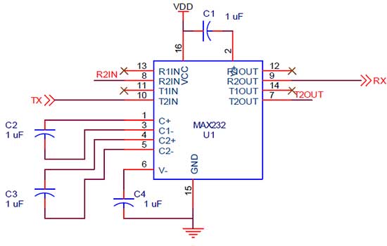
Fig.3 MAX232 Connection diagram
R2IN line is connected with RXD pin of 10-way DIP switch and T2OUT is connected with RXD pin of 10-way DIP switch. RC6, RC7 are PORTC’s 6th and 7th pins respectively. The capacitors may differ from 1uF to 10uF but 1uF is preferred for better result.
For Serial communication
- Load the hex file “SimpleUsart.hex” into Icprog. See section 1.1 for how to load program into PIC.
- Connect Serial cable with DB9 connector on the PIC Evaluation Board.
- Configure Your PC Hyper Terminal for the specified baud rate and others.
- Turn on DIP switch pins RXD, TXD, MCLR pins. Turn OFF remaining pins.
- See the result by pressing any one key from your keyboard.
Configuring the Hyper Terminal:
1. Click start >> Programs >> Accessories >> Communications >> Hyper Terminal
2. Enter a Name at the Name field and click OK
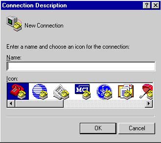
3. Select COM1 in the Connect using drop down box (select COMx if more than one Port)
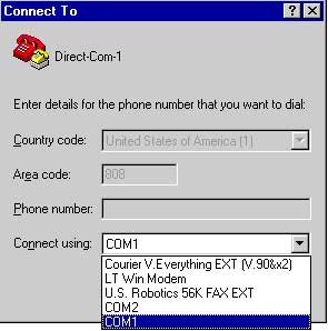
4. Select 9600, 8, none, 1, none respectively or click “Restore defaults” button. Click OK.
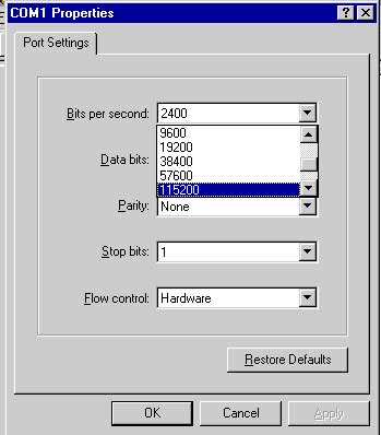
5. Now Port is configured as we needed.
Single channel ADC:
PIC Evaluation Board has single channel analog source for ADC interfacing. Analog source might be LM35, LM335, POT or any other device which is compatible with the above devices.
Follow the steps below for ADC interfacing,
- Load the hex file “adc_serial.hex” on PIC. See section ISP for how to load program into PIC.
- Connect Serial cable with DB9 connector on the PIC Evaluation Board.
- Turn on ADC pin in DIP switch. This will connect Analog device with PORTA.0 pin.
- Turn on DIP switch pins MCLR, RXD, TXD and connect serial Port cable
- See the output in your PC Hyper Terminal.
External reset at MCLR
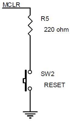
Fig.5 External Reset
Fig.5 shows External reset supplied by a Push Button switch to the MCLR pin of PIC. The function of above reset circuit is to reset the PIC and bring back to its initial position. Reset pulse is applied when MCLR pin is supplied by an active low signal. This circuit is connected to the microcontroller via DIP switch MCLR pin.
External Interrupt:
PIC has 14 sources of interrupt. Out of which 12 are internal interrupts and the remaining 2 are external interrupts. PORTB pin RB0 serves as external interrupt port pin. Falling/Rising edge on RB0 will generate an interrupt. Fig.4 shows RB0 interrupt connection diagram, INT_DIP is connected to INT pin of 10-way DIP switch.
For RB0 interrupt Demo
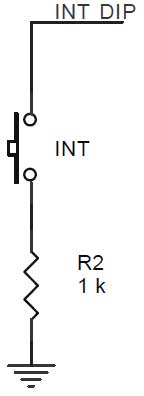
Fig.4 Port On-Change Interrupt
I/O connections:
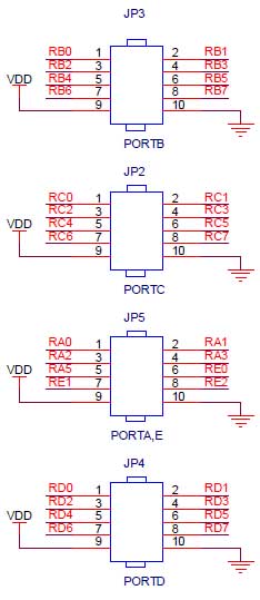
Fig.6 I/O connections
PIC has 33 general purpose I/O pins. PIC Evaluation Board provides access to all I/O pins except RA4 open drain pin. These I/O lines are connected via Four FRC connectors. All are 10 pin connectors with 9th and 10th pins are connected to VDD and VSS respectively. JP2, JP3, JP4 are connected to PORTC, PORTB, PORTD respectively. PORTA and E are sharing a single connector JP5.
10-wire FRC cable provided with this board will be used for interconnection with other externaldevices. Some of the IO lines are shared with onboard peripherals like LCD, Relay Driver unit etc.
LCD display:
PIC evaluation Supports 16×2 LCD display. Connector J1 holds LCD display. J2 is for Backlight selection. PORTE lines 0, 1 and 2 are Control signals and PORTD is data lines.
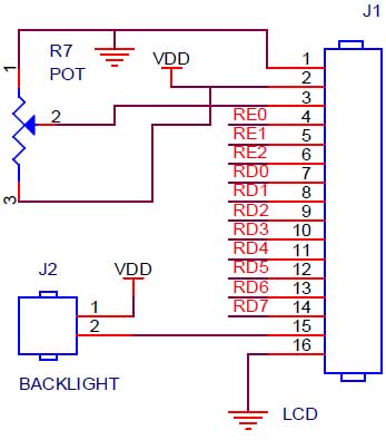
Fig.7 LCD connections
For LCD demo,
- Load the hex file “LCD.hex” into PIC.
- Turn on DIP switch pin MCLR .
- Put jumper on J2(if back light required)
- Watch the result on LCD
Relay Driver:
Jumper J3, J4 and J5 are connected to PORTC pins RC0, RC1 and RC2 respectively. J6, J7 and J8 are outputs to Relay. The relay to be connected must have VDD or VSS connected on the other end.
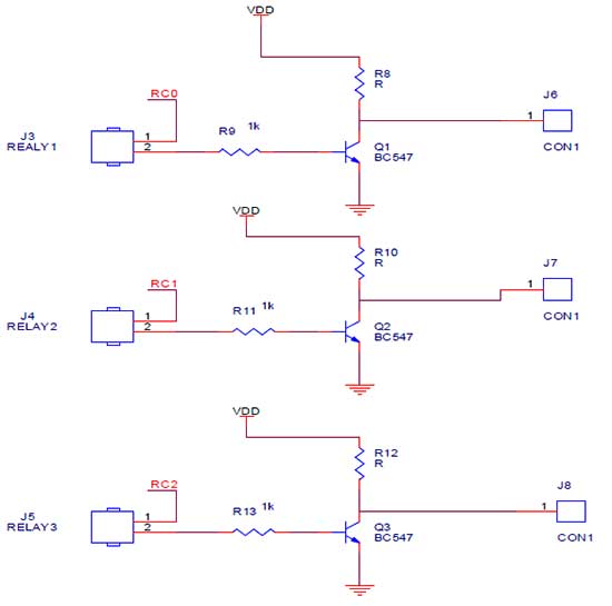
Fig.8 Relay Driver
For Relay Demo,
- Load the hex file “BuzRelay.hex” into PIC.
- Connect Serial cable with DB9 connector on the PIC Evaluation Board.
- Turn on DIP switch pin MCLR, RXD, TXD.
- Open Hyper terminal and Press reset once if the Hyper terminal is blank.
- Press 1 to 6 to turn ON and OFF devices.
- For Output, measure the voltage on j6,j7 and j8 or connect an LED on j6,j7 and j8
BURNING INTO PIC
Programming a involves three steps,
- Configuration of Software
- Configuration of Hardware
- Burning a Program into PIC
Configuration of Software:
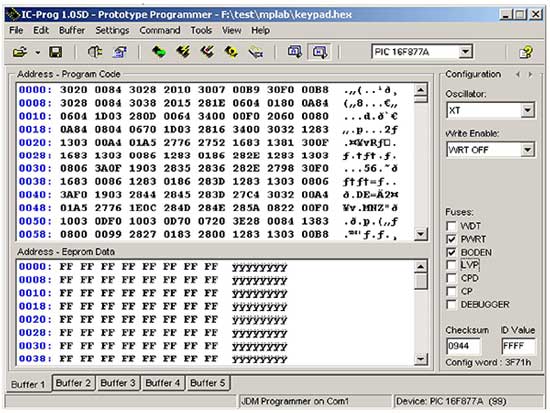
The burning software we are using for our PIC Evaluation Board is Ic-prog. Fig.2.1 shows Ic-prog software. When opening for the first time, we have to configure ic-prog as necessary. Configuration includes selection of Ports, Interfaces, I/O delays, Driver installation for WINNT Etc.
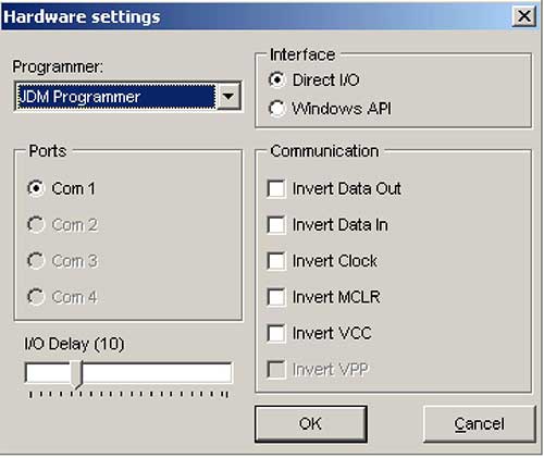
Fig.2.1 Hardware Settings
Choose the following from Settings >> Hardware Menu,
- JDM programmer from the Programmer List Box.
- Com1 as your Programming port.
- Direct I/O as interface to our hardware.
- Left unchanged the I/O delay box.
Enable driver by enabling Enable NT/2000/XP Driver Check box from Settings >> Options >> Misc Menu. Message box will be displayed to restart ic-prog, click YES to restart icprog. After restart choose Process Priority as necessary. Changing Process Priority will adjust only the I/O delay; it will not affect programming flow. Left this tab unchanged.
Fig.2.2 shows driver installation dialog box.
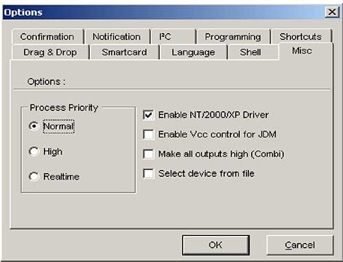
Fig.2.2 Driver Installation for WINNT
Configuration of Hardware:
The other important thing when programming PIC is checking hardware connection. This can be done by enabling DATA, CLK, MCLR, and VCC check boxes from Settings >> Hardware Check menu, and verifying the corresponding PIC pins.
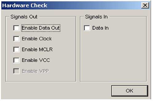
Fig.2.3 Hardware Verification dialog Box
From the dialog box,
- Check the Enable Data Out check box, Turn on DIP switch pins DATA(5,6) and measure the voltage between GND and RB7 pin, there should be an approximate positive voltage of 2.5v should be present at RB7.
- Check the Enable Clock check box, Turn on DIP switch pin CLK(3) and measure the voltage between GND and RB6 pin, there should be an approximate positive voltage of 2.5v should be present at RB6.
- Check the Enable MCLR check box, Turn on DIP switch pin VPP(4) and measure the voltage between GND and MCLR pin, there should be a positive voltage of >10 should be present at MCLR pin of PIC.
- There is no need for checking VCC because the supply is given via an xternal power supply.
Burning a Test Program into PIC:
Burning a test program into PIC can be done by simply opening a test file, selecting a device and configuration bits, clicking the Program Icon in Ic-prog. Follow the steps given in chapter 1.1.