User Manual for PIC 16F/18F Development Kit
INTRODUCTION
The PIC is a Development Board which demonstrates the capabilities of the 40-pin PIC16and PIC18 devices. The PIC development Board can be used stand-alone board built with an in-circuit USB programmer. Sample programs are provided to demonstrate the unique features of the supported devices.
The PIC Development Board kit comes with the following:
- PIC Development Board
- Sample devices (16F877A)
- CD-ROM, which contains: a) Sample programs b) PIC Development Board kit User’s Guide
PIC Development Board
The PIC Development Board has the following hardware features:
- 40-pin ZIF socket.
- +12V and +5V regulators for direct input from 15V, 500 mA AC/DC wall adapter
- RS-232 socket and associated hardware for RS-232 interface.
- ICSP USB 2.0 Programmer with busy LED indication
- Two 5 KΩ pot and one LM35 for devices with analog inputs.
- Four push button switches for external interrupts and Reset.
- Red power-on indicator LED.
- Eight red LEDs connected to 10 Pin FRC.
- A 10 MHz crystal oscillator.
- Microchip 25C040 Serial SPI EEPROM.
- Atmel AT24c04 Serial I2C EEPROM
- Dallas DS1307 Serial I2C Real-time Clock
- LCD display with backlight Selection Jumper.
- Piezo buzzer and OEM Relay.
- Dallas DS1820 thermal sensor.
- Four 7Segment multiplexed display
- ULN2803 driver for unipolar Stepper motors
- 4×4 matrix keypad
- 8 way DIP switch for digital input
- 8 way Configuration DIP switch for multiple operation
PIC Development Board HARDWARE

SAMPLE DEVICES
One FLASH device is included. The device types may change, but will generally include PIC16 and PIC18 40-pin DIP devices.
SAMPLE PROGRAMS
The PIC Development kit includes a CD-ROM with sample programs. These programs may be used with the included sample devices. For each type of device (PIC16 or IC18), demo source code with compiled Hex file is provided.
PIC Development BOARD LAYOUT
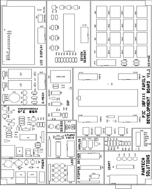
Hardware Details
SOCKETS
40 Pin ZIF socket is provided for the processor. Microcontroller can be removed from the board easily. This socket is intended to use our development board as programmer to program other IC’s.
10 pin FRC box type connectors: This will be found in each section of PIC 16F/18F development board. A 10 pin FRC cable is used to make connection with the main board section. Any 8 bit port of microcontroller can be used for interconnection. Ports having less than 8 bits are used as control signals for various sections.
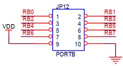
Pins 1-8 are Data Pins. Pin 9 is VDD and the Pin 10 is GND. All 10 Pin FRC connectors will follow the same rule.
JUMPER SETTINGS
| JUMPER | DESCRIPTION |
| J6 | Relay supply select :Connecting INT and +5v will select internal supply. Connecting EXT and +5v will select external supply if connected GND is a common GND for external |
| J7 | LCD backlight selection:; Put jumper if backlight needed |
| J8 | Interrupt Edge selection: Middle and FE >>Falling EdgeMiddle and RE >> Rising Edge |
| J9, J10, J11 | Interrupt Port Pin Selection: Middle and RB >>Interrupt on PORTB Middle and RC >>Interrupt on PORTC |
| J13 | Digital Input logic selection: +5v-Logic High, GND-Logic low Input |
CONFIG SWITCH
SW1: 8 way Multifunctional switch
| DIP SWITCH PIN | DESCRIPTION |
| ADC | Supply select for Analog channels |
| DS1820 | Connects DS1820 temperature sensor to RC0 |
| CS, SCL, MISO, MOSI | SPI and I2C Selection pins: Turn ON SCL and MISO for I2C operation Turn all the pins for SPI operation |
| TXD, RXD | RS232 communication transmit, receive pins |
POWER SUPPLY
The external power can be AC or DC, with a voltage (15V, 1A output). The PIC board produces +5V using an LM7805 voltage regulator, which provides supply to the peripherals. Power supply is controlled through slide switch SW2.
Installation Notes
Installing MPLAB IDE and Hi-tech C Compiler
Open up the user CD comes with PIC Microcontroller Board, Navigate to MPLAB IDE Folder
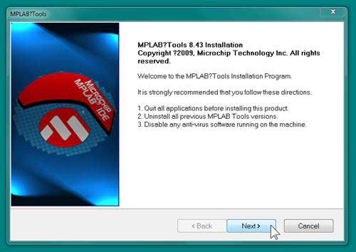
Double Click Setup.exe and Click >> Next
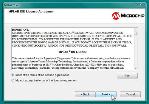
3. Click >> I accept the terms of the license agreement and Click >> Next
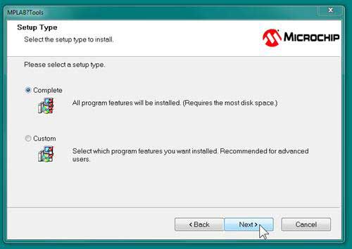
4. Select >> Complete check box and Click >> Next
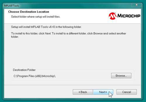
5. Click >> Next
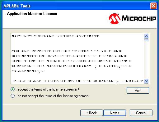
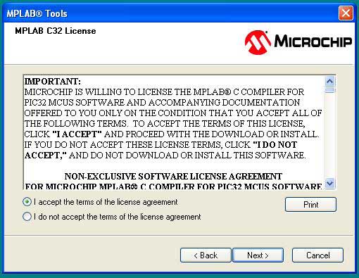
6. Click >> I accept the terms of the license agreement for both Application Maestro as well as MPLAB c32 windows and Click >> Next, Next
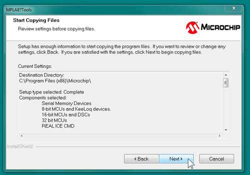
7. Click >> Next to Start Copying Files
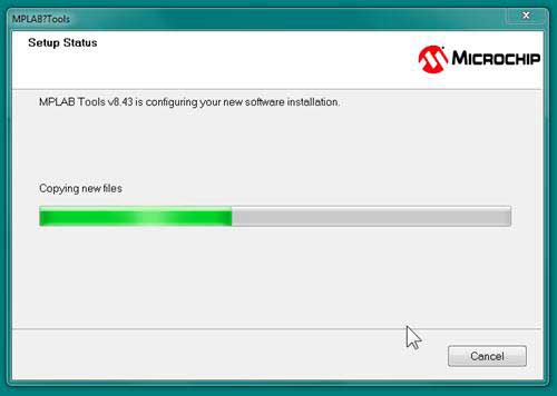
8. Now the MPLAB IDE setup will Progress
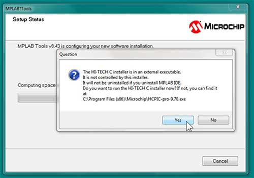
9. After finishing installation MPLAB IDE, it will prompt for HI-TECH C Installation. Click >> Yes
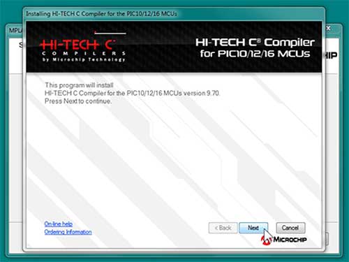
10. Click >> Next
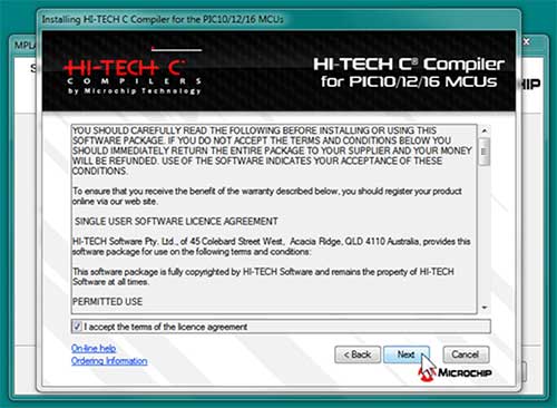
11. Click >> License agreement Check box and Click >> Next
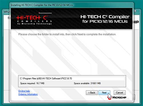
12. Click >> Next
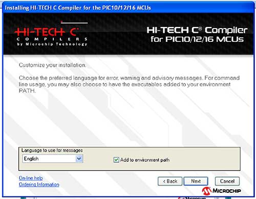
13. Check >> Add to environment path and Click >> Next
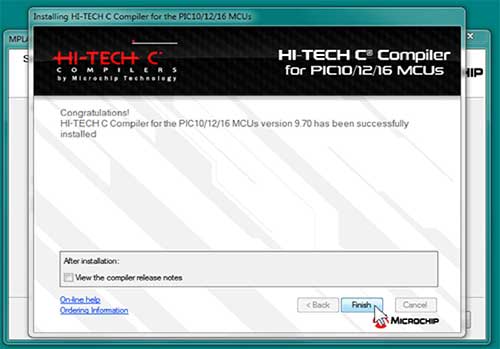
14. Click >> Finish
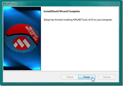
15. Click >> Finish to InstallShield Wizard Complete
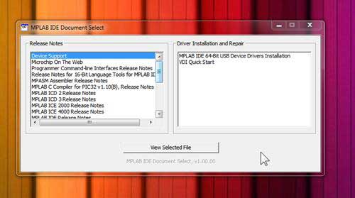
16. Just Close the MPLAB IDE Document Support
Creating a Project on MPLAB IDE
1. Double Click the MPLAB IDE v8.xx from desktop
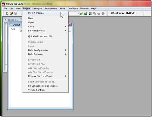
2. To create a new project, Click >> Project and Project Wizard.
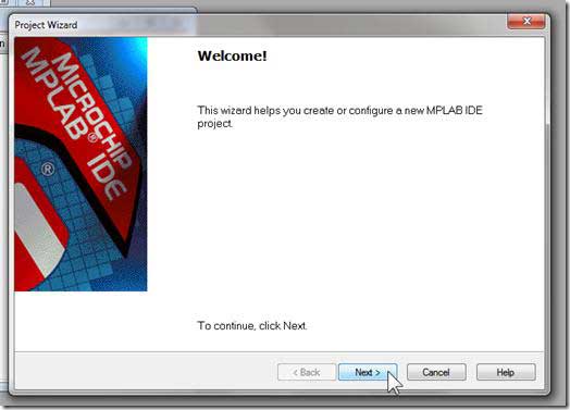
3. At the first page of Project Wizard, Click >> Next.
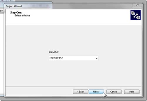
4. Step ONE: Next, you will need to select the device for your project. For this demonstration I will use PIC16F877A as the device.
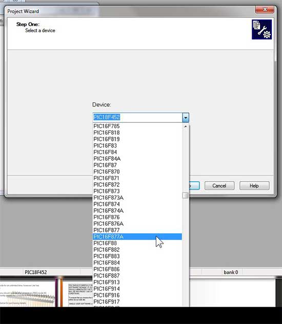
5. After selecting the device, click >> Next
6. Step TWO: Select the Compiler for your Project.
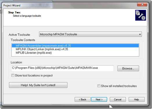
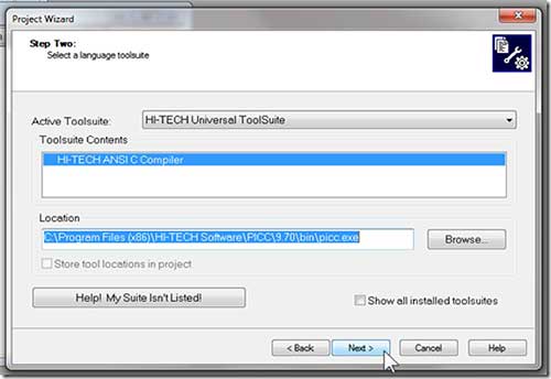
7. Click the Active Toolsuite and select HI-TECH Universal ToolSuite.
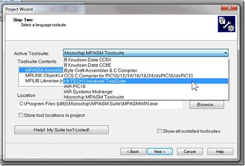
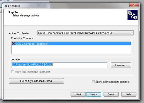
8. There should not be any red “X” mark (For those with the red “X”, please reinstall the HI-TECH C for PIC 10/12/16). Click Next to continue.
Example: See the “Red X” mark that appears before CCS C compilers
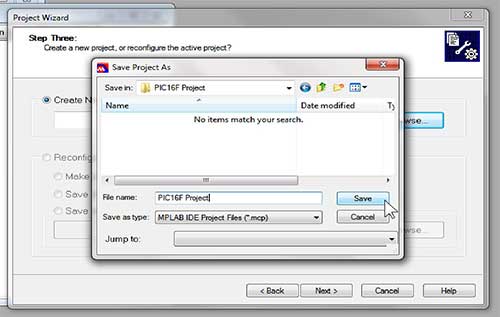
9. Step Three: Select the directory to store your project and your project name.
- Click on Browse to open a browser where you choose the directory and the project name.
- It is advised that you use a new folder for a new project, and all the coding file (c file, h file, asm file) should be stored under the same folder.
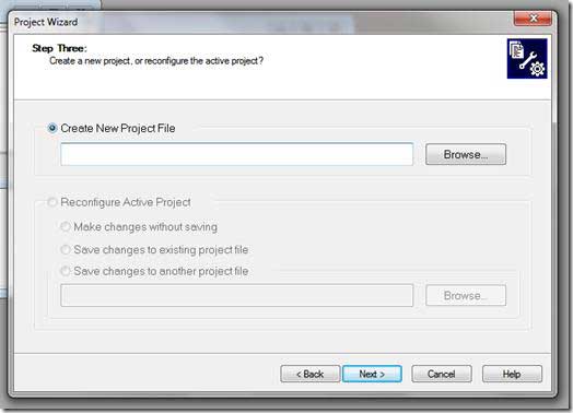
10. Now enter the Project Name and Click >> Save
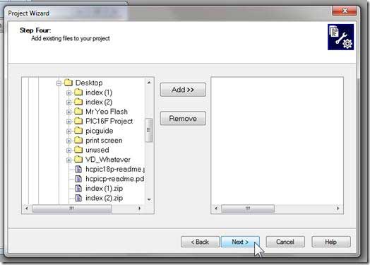
11. Click >> Next to the following window
12. Step four, Add existing file to your project. Just Skip this by clicking Next.
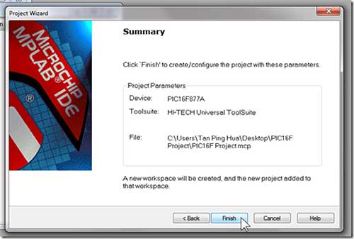
13. You have successfully created the project. Click Finish to continue.
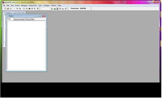
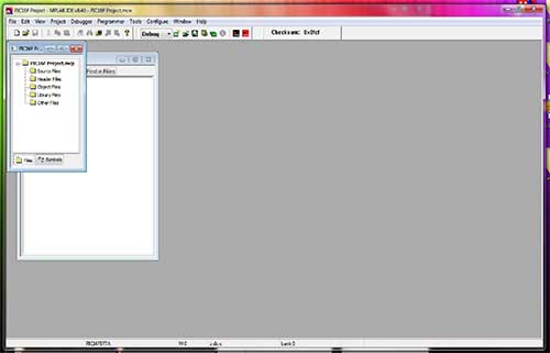
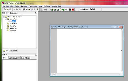
14. The project that you create will be open after you successfully create it, and this is what you will see at the IDE, a Project window and an Output window.
If you don’t have these windows on your IDE, you can always enable it back by clicking View >> Click the Project and Output.
15. Click on the icon (New File) to create a new file.
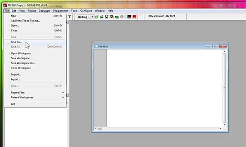
16. After creating the new file, now save it. Click File and Save As.
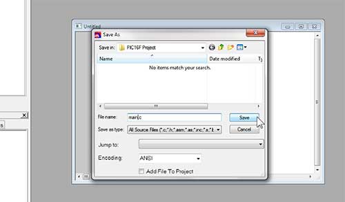
17. To save it as a c file, put a “.c” at the File name of the file to save. Save the file in the same directory of your project.
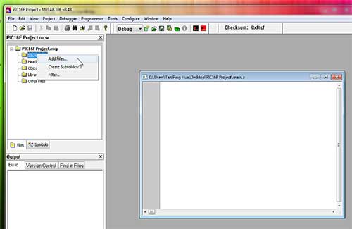
18. Now include the “.c” file into your project, right click at the Source File, and click Add Files.
19. Select the file that is being saved.
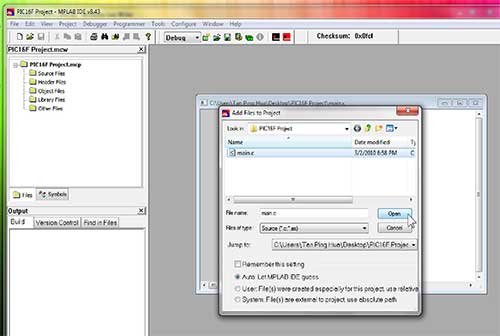
20. Now the code file “main.c” is added to your project. You can see that it is shown under the Source Files at the Project window.
21. To compile the project, click on the Build Project button or the Rebuild project button.
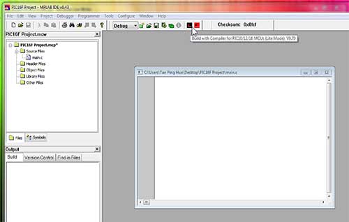
22. Now you successfully created all the things. Now write your code and Compile it.
Configuring Programmer for PIC Development Board
- First attach the PIC Microcontroller Development Board with PC via USB cable.
- Connect the 15V AC/DC Adapter with Development Board.
- Turn ON the Power Switch.
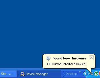
- Wait until the Pickit2 Finishes Driver Installation. If the driver not detected just try to reconnect or RESE-Tart your system, then try again.
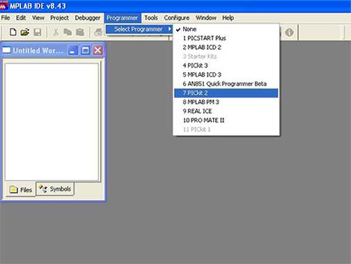
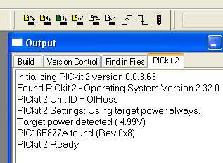
5. After Finishing the Hardware driver installation. Open MPLAB IDE. Select Programmer >> Select Programmer >> PICkit2
6. If the Kit is properly connected, you can see the Pickit2 Icon set on the Toolbar (Yellow Set) and the PICkit2 Ready Message. Very First icon is used for “Programming the device”.
7. Finally open our Example Programs, Burn into the controller, do the hardware connection as per Chapter 2 and See the result.
Error 1: MPLAB may throw “Write Failure-Get lost Error”. If it does, follow the instructions below,
- Unplug the Power supply from target board
- Close MPLAB
- Plug the AC/DC adapter
- Reopen MPLAB
Error 2: MPLAB may throw “target not found” error, If it does, follow the instructions below
- Ensure whether the PIC microcontroller placed properly in ZIF jacket.
- In Configure–>Select device, ensure PIC16f877A (or any) is selected.
Error 3: MPLAB may throw “Verified Failed” error, due to the following
- Hex File may be old, so compile the project once and try Programming.
- Faulty microcontroller device, Replace it with new one.
Note *: If the error still retains check your windows firewall or antivirus software to allow this MPLAB and Pickit2 programmer.
Example Programs and Connections
SEVEN SEGMENT
I2C EEPROM
ADC
DATA EEPROM
| NOTES |
| This Source code is written to access the Internal EEPROM of PIC Microcontroller. So No hardware connection is needed.Connect Serial cable between USART Section in the Board and PC.“Hello World” will be displayed in HyperTerminal Click “Programmer >> Read EEDATA” in MPLAB to see the contents of Internal EEPROM |
DIGITAL INPUTS
DS1307
DS1820
INPUT CAPTURE
INTERRUPT
KEYPAD
KEYPAD_LCD
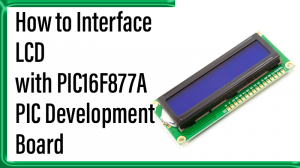
LCD
LED
PWM
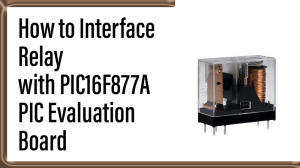
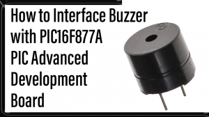
RELAY and BUZZER
SPI EEPROM
STEPPER MOTOR
USART
USART with PRINTF
Setting up HyperTerminal
HyperTerminal is automatically installed under Programs >> Accessories,
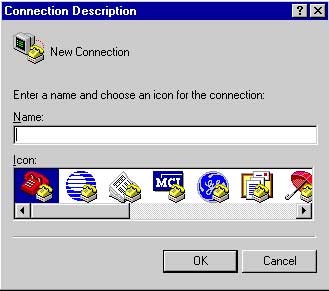
1. Click Start >> Programs >> Accessories >> Communications >> HyperTerminal
- Enter Name (e.g. Com1_9600) and choose any one ICON.
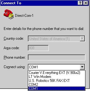
2. Click the drop-down arrow by Connect Using >> COM1 >> Click OK
3. COM1 Properties, Port Settings
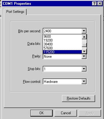
- Bits per Second: select 9600 (or desired baud rate)
- Data Bits: select 8
- Parity: select None
- Stop Bits: select 1
- Flow Control: select none
- Click OK
4. Now you get the HyperTerminal window.