
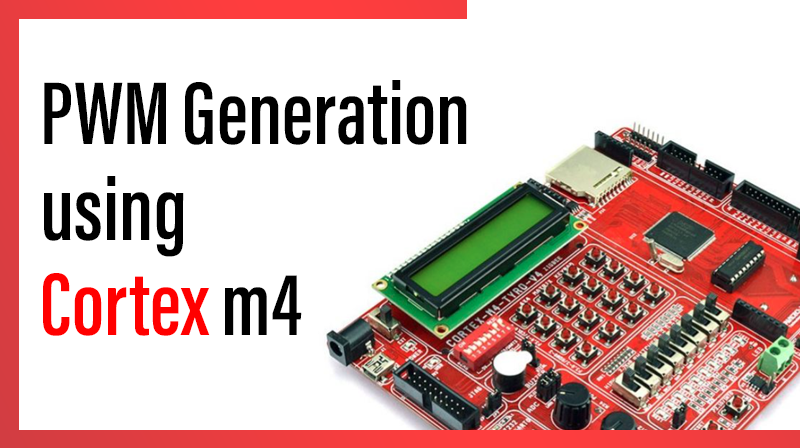
PWM Generation using Cortex m4
This blog post describes how to generate a PWM with variable duty cycle.the processor we used is NXP LPC 4088 .
Steps for PWM Generation using Cortex M4
- Power: In the PCONP register, set bit PCPWM1
- Configure pins P2.0 to P2.5 for PWM using IOCON_P2_0 to IOCON_P2_5.
- Select the single edge mode of PWM
- Select the clock source and clock value for PWM (peripheral clock).
- Set match value for PWM match channel 0 (Frequency of PWM ie period)
- Select and update the duty cycle for each channel (Match registers)
- Enable PWM Channel Output
- Reset the counter to zero
PWM Generation using Cortex m4- C source code
#include "LPC407x_8x_177x_8x.h"

#define PWMPRESCALE 30		//30 PCLK cycles to increment TC by 1 i.e 1 Micro-second

void init_pwm(void);
void delay_ms(long ms) ;

int main(void)
{
		init_pwm();
		while(1);
}

void init_pwm(void)
{
	//1. set bit PCPWM1
		LPC_SC->PCONP |= (1 << 6); 										/* enable power to PWM1*/

	//2. Configure Pins P2.0 to P2.5 for PWM using IOCON_P2_0 to P2_5
		LPC_IOCON->P2_0 =  1;        									/* Pin P2.0 to P2.6 used as PWM */
		LPC_IOCON->P2_1 =  1;
		LPC_IOCON->P2_2 =  1;
		LPC_IOCON->P2_3 =  1;
		LPC_IOCON->P2_4 =  1;
		LPC_IOCON->P2_5 =  1;

		LPC_PWM1->PCR  = 0x0; 									// Step-3. Select Single Edge PWM - by default its single Edged so this line can be removed
		LPC_PWM1->PR   = PWMPRESCALE-1; 				// Step-4. 1us resolution (30MHz/30)=1MHz
		LPC_PWM1->MR0  = 10000;      						// Step-5. 10ms=10000us period duration ie 100Hz

		//6.Select the duty cycle for each channel
		LPC_PWM1->MR1  = 9500; 									// 9.5ms - pulse duration i.e Duty=95%
		LPC_PWM1->MR2  = 8000; 									// 8.0ms - pulse duration
		LPC_PWM1->MR3  = 6000; 									// 6.0ms - pulse duration
		LPC_PWM1->MR4  = 3000; 									// 3.0ms - pulse duration
		LPC_PWM1->MR5  = 1500; 									// 1.5ms - pulse duration
		LPC_PWM1->MR6  = 500; 									// 0.5ms - pulse duration i.e Duty=5%
		LPC_PWM1->LER  = 0x7F; 									// Update Period and Duty cycle

		//7.Enable PWM Channel Output
		LPC_PWM1->PCR  = (0x3F<<9); 						// enable PWM1 to PWM6 output
		LPC_PWM1->TCR  = (1<<0) | (1<<3); 			// enable counters and PWM Mode

		//8.Reset the Counter
		LPC_PWM1->TCR  = (1<<1) ; 							// Reset PWM TC & PR
}

void delay_ms(long ms) 					// delay 1 ms per count @ CCLK 120 MHz
{
		long i,j;
		for (i = 0; i < ms; i++ )
		for (j = 0; j < 26659; j++ );
}

void delay_ms(long ms)
{
long i,j;
for (i = 0; i < ms; i++ )
for (j = 0; j < 26659; j++ );
}
from the above code why we use 26659?