Lesson 3: Learn FPGA – PWM Generation in Spartan3an Stick Board
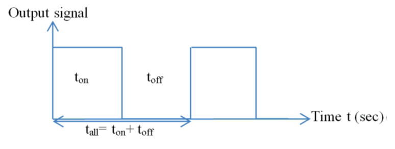
As we get LED’s counting in our previous blog post, now we get our hands to PWM generation. PWM stands for Pulse Width Modulation. PWM mostly used to control analog devices with digital pulse switching between ON/OFF states. The combination of ON and OFF time gives the duty cycle of pulse. Mostly used to control switching devices to save power loss.
Figure 1: PWM Pulse
PWM can be easily generated with FPGA. As we know FPGA is a parallel architecture which triggers concurrent output, it helps us to get many PWM output at the same time. As a result we can control more motors.
Now let’s take PWM output with duty cycle with 1ms.
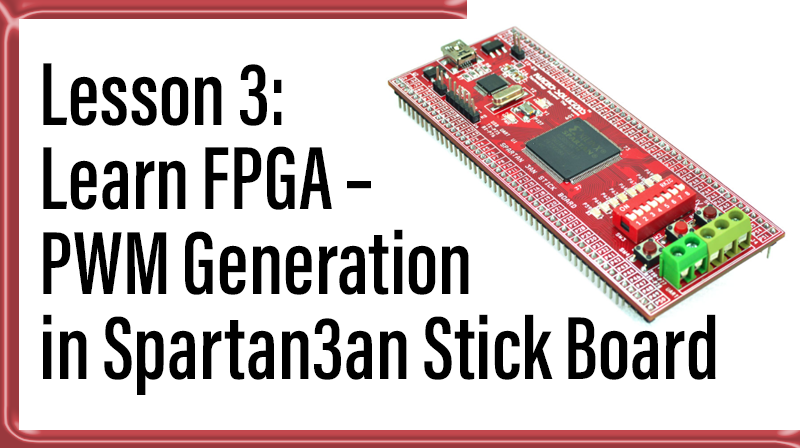
Spartan3an FPGA Stick Board contains 50 MHz Clock input.
Clock Frequency = 50 MHz
Clock in time Period = 20 ns
Duty Cycle of PWM (1ms) = 20ns x 50000 = 1ms = tall.
tall = ton + toff as shown in figure.
VHDL code can be easily done by clock divider as similar to Binary counter in previous tutorial.
library ieee;

use ieee.std_logic_1164.all;

use ieee.std_logic_unsigned.all;

entity PWM is

port(Clock, RESET : in  std_logic;

PWM_OP : out std_logic);

end PWM;


architecture archi of counter is

signal count: std_logic_vector(32 downto 0);

signal tmp: std_logic;

begin


process (Clock, RESET)

begin

if (RESET='1') then

tmp '0');

elsif Rising_edge(Clock) then

if count < “110000110101000” then
count <= count + 1;

else

tmp <= not tmp;

count ‘0’);

end if;

end if;

end process;

PWM_OP <= tmp;

end archi;
From the above code, when count value reach “110000110101000” = 25000 then PWM output get inverted priceofcialis through tmp signal.
We can easily interface DC motor with L293D IC in spartan3an Stick Board.
Buy Spartan3an Stick Board to Demonstrate above tutorial.
https://www.pantechsolutions.net/cpld-fpga-boards/spartan3an-fpga-project-kit


