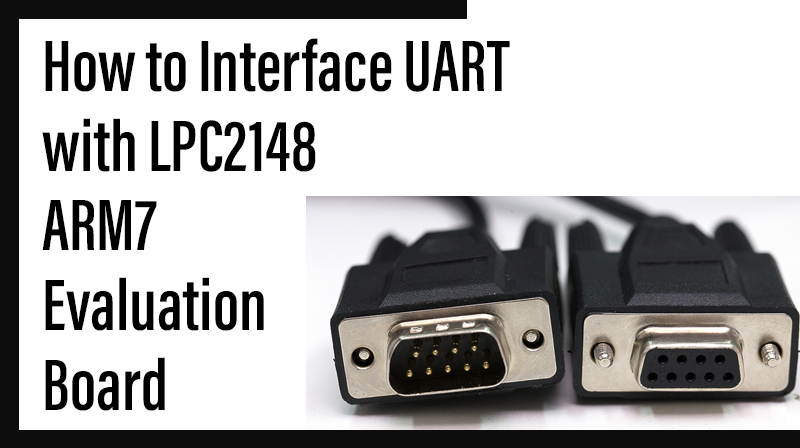
How to Interface UART with LPC2148-ARM7 Evaluation board
The ARM7 LPC2148 Evaluation Board is specifically designed to help students to master the required skills in the area of embedded systems. The kit is designed in such way that all the possible features of the microcontroller will be easily used by the students. The kit supports in system programming (ISP) which is done through serial port.
NXP’s ARM7 ( LPC2148), ARM Evaluation Kit is proposed to smooth the progress of developing and debugging of various designs encompassing of High speed 32-bit Microcontrollers.
UART
UART (Universal Asynchronous Receiver Transmitter) are one of the basic interfaces which provide a cost effective simple and reliable communication between one controller to another controller or between a controller and PC.
RS-232 Level Converter
Usually all the digital ICs work on TTL or CMOS voltage levels which cannot be used to communicate over RS-232 protocol. So a voltage or level converter is needed which can convert TTL to RS232 and RS232 to TTL voltage levels. The most commonly used RS-232 level converter is MAX232.
This IC includes charge pump which can generate RS232 voltage levels (-10V and +10V) from 5V power supply. It also includes two receiver and two transmitters and is capable of full-duplex UART/USART communication.
☞RS-232 communication enables point-to-point data transfer. It is commonly used in data acquisition applications, for the transfer of data between the microcontroller and a PC.
☞The voltage levels of a microcontroller and PC are not directly compatible with those of RS-232, a level transition buffer such as MAX232 be used.
Interfacing UART
Fig. 1 shows how to interface the UART to microcontroller. To communicate over UART or USART, we just need three basic signals which are namely, RXD (receive), TXD (transmit), GND (common ground). So to interface UART with LPC2148, we just need the basic signals.

Interfacing UART with LPC2148
Display a text in PC from LPC2148 Evaluation Board by using UART module. In LPC2148 Evaluation Board contains two serial interfaces that are UART0 & UART1. Here we are using UART1. The Transmitter pins send the data into PC and the receiver pin receives the data from PC.
Pin Assignment with LPC2148
Circuit Diagram to Interface UART with LPC2148

Source Code
The Interfacing UART with LPC2148 program is very simple and straight forward, which display a text in PC from LPC2148 Evaluation Board through UART1. Some delay is occurring when a single data is sent to PC.
C Program to display a text in PC from LPC2148
****************************************************************************************************
Title : Program to display a text in PC from through UART1
*****************************************************************************************************
#define CR     0x0D
#include
void init_serial (void);
int putchar (int ch);
int getchar (void);
unsigned char test;
//<<<<<<<<<<<<<<<<<<<<<<<<<<<<<<<<<<<	Code Begins Here	>>>>>>>>>>>>>>>>>>>>>>>>>>>>>>>>>>>>

int main(void)
{
  char *Ptr = "*** UART0 Demo ***\n\n\rType Characters to be echoed!!\n\n\r";
  VPBDIV = 0x02;						//Divide Pclk by two
 init_serial();

	while(1)
	{
		while (*Ptr)
		{
			putchar(*Ptr++);
		}

		putchar(getchar());					//Echo terminal
	}
}

//<<<<<<<<<<<<<<<<<<<<<<<<< Serial Initialization >>>>>>>>>>>>>>>>>>>>>>>>>>>>
void init_serial (void)			  /* Initialize Serial Interface       */
{
  PINSEL0 	= 0x00000005;         /* Enable RxD0 and TxD0              */
  U0LCR 	= 0x00000083;         /* 8 bits, no Parity, 1 Stop bit     */
  U0DLL 	= 0x000000C3;         /* 9600 Baud Rate @ 30MHz VPB Clock  */
  U0LCR 	= 0x00000003;         /* DLAB = 0                          */
}

//<<<<<<<<<<<<<<<<<<<<<<<<<<< Putchar Function  >>>>>>>>>>>>>>>>>>>>>>>>>>>>>>

int putchar (int ch) 			  /* Write character to Serial Port    */
{

  if (ch == '\n')  {
    while (!(U0LSR & 0x20));
    U0THR = CR;              	   /* output CR */
  }
  while (!(U0LSR & 0x20));
  return (U0THR = ch);
}

//<<<<<<<<<<<<<<<<<<<<<<<<<<<< Getchar Function >>>>>>>>>>>>>>>>>>>>>>>>>>>>>

int getchar (void) 				/* Read character from Serial Port   */
{

  while (!(U0LSR & 0x01));
  return (U0RBR);

}
To compile the above C code you need the KEIL software. They must be properly set up and a project with correct settings must be created in order to compile the code. To compile the above code, the C file must be added to the project.
In Keil, you want to develop or debug the project without any hardware setup. You must compile the code for generating HEX file. In debugging Mode, you want to check the port output without LPC2148 Evaluation Board.
The Flash Magic software is used to download the hex file into your microcontroller IC LPC2148 through UART0.
Testing the UART1 with LPC2148
Give +3.3V power supply to LPC2148 Evaluation Board; the serial cable is connected between the LPC2148 Evaluation Board and PC. Open the Hyper Terminal screen, select which port you are using and set the default settings. Now the screen should show some text messages.
If you not reading any text from UART0, then you just check the jumper connections & just check the serial cable is working. Otherwise you just check the code with debugging mode in Keil. If you want to see more details about debugging just see the videos in below link.
☞How to Create & Debug a Project in Keil
General Information
☞For proper working use the components of exact values as shown in Circuit file. Wherever possible use new components.
☞Solder everything in a clean way. A major problem arises due to improper soldering, solder jumps and loose joints.
☞Use the exact value crystal shown in schematic.
☞More instructions are available in following articles