
How to Interface Traffic Light with LPC2148 ARM7 Development Board
The ARM7 LPC2148 Development Board is specifically designed to help students to master the required skills in the area of embedded systems. The kit is designed in such way that all the possible features of the microcontroller will be easily used by the students. The kit supports in system programming (ISP) which is done through serial port.
NXP’s ARM7 (LPC2148), ARM Development Kit is proposed to smooth the progress of developing and debugging of various designs encompassing of High speed 32-bit Microcontrollers.
Traffic Light Control
Traffic lights, which may also be known as stoplights, traffic lamps, traffic signals, signal lights, robots or semaphore, are signaling devices positioned at road intersections, pedestrian crossings and other locations to control competing flows of traffic.
About the colors of Traffic Light Control
Traffic lights alternate the right of way of road users by displaying lights of a standard color (red, yellow/amber, and green), using a universal color code (and a precise sequence to enable comprehension by those who are color blind).
In the typical sequence of colored lights:
☞Illumination of the green light allows traffic to proceed in the direction denoted,
☞Illumination of the yellow/amber light denoting, if safe to do so, prepare to stop short of the intersection, and
☞Illumination of the red signal prohibits any traffic from proceeding.
Usually, the red light contains some orange in its hue, and the green light contains some blue, for the benefit of people with red-green color blindness, and “green” lights in many areas are in fact blue lenses on a yellow light (which together appear green).
Interfacing Traffic Light with LPC2148
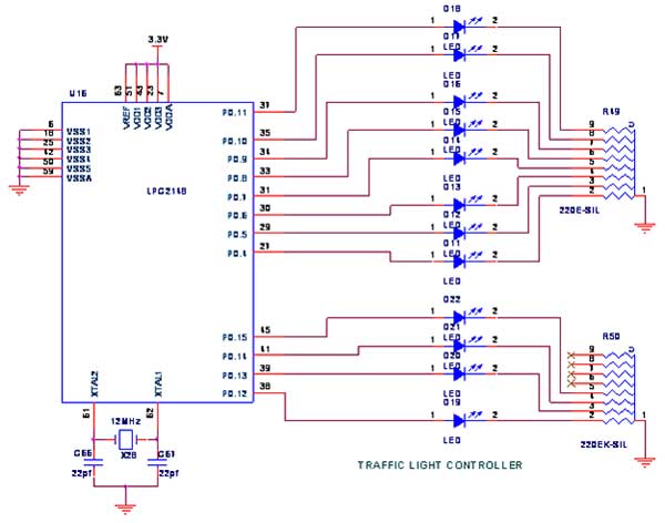
The Traffic light controller section consists of 12 Nos. point leds are arranged by 4Lanes in LPC2148 Development Board. Each lane has Go(Green), Listen(Yellow) and Stop(Red) LED is being placed.
Pin Assignment with LPC2148
Circuit Diagram to Interface Traffic Light with LPC2148
Source Code
#include
void Delay(int); 			//Delay Routine
void SupDelay(int); 		//Delay Routine

void main()
{
	PINSEL2 = 0X00000000; // P1.24 TO P1.31 as GPIO
	IO0DIR = 0X0000FFF0; // p1.24 TO P1.31 Configured as Output port.

	while(1)
	{

		IO0SET=0x00003090;	  // D19 GREEN , ALL RED
		Delay(500);

		IO0CLR=0x00001000;

		IO0SET=0x00002890;
		SupDelay(100);

		IO0CLR=0x000002890;
		Delay(1);

		IO0SET=0x00008490;	  // D22 GREEN , ALL RED
		Delay(500);

		IO0CLR=0x00008000;

		IO0SET=0x00004490;
		SupDelay(100);

		IO0CLR=0x00004490;
		Delay(1);

		IO0SET=0x000024C0;   // D13 GREEN ,ALL RED
		Delay(500);

		IO0CLR=0x00000040;

		IO0SET=0x000024A0;
		SupDelay(100);

		IO0CLR=0x000024A0;
		Delay(1);

		IO0SET=0x00002610;	//D16 GREEN ,ALLRED
		Delay(500);

		IO0CLR=0x00000200;


		IO0SET=0x00002510;
		SupDelay(100);

		IO0CLR=0x00002510;
		Delay(1);


	}
}

void Delay(int n)
{
	int p,q;

	for(p=0;p<n;p++)
	{
		for(q=0;q<0xFFF0;q++);
	}
}

void SupDelay(int n)
{
	int p,q;

	for(p=0;p<n;p++)
	{
		for(q=0;q<0xFFF0;q++);
		for(q=0;q<0xFFF0;q++);
	}
}
The Interfacing Traffic Light Control with LPC2148 program is very simple and straight forward, which controls Traffic Light in certain time period. The C program is written in Keil software.
To compile the C code, you must need the KEIL software. They must be properly set up and a project with correct settings must be created in order to compile the code. To compile the C code, the C file must be added to the project.
In Keil, you want to develop or debug the project without any hardware setup. You must compile the code for generating HEX file. In debugging Mode, you want to check the port output without LPC2148 Development Board.
The Flash Magic software is used to download the hex file into your microcontroller IC LPC2148 through UART0.
Testing the Traffic Light Controller with LPC2148
Give +3.3V power supply to LPC2148 Development Board; the LED is connected with LPC2148 Development Board. When the program is downloading into LPC2148 in a Development Board, the LED output is working that some LED is ON and some LED is OFF in the Traffic Light format.
If you not reading any output from LED, then you just check the jumper connections & check the LED is working. Otherwise you just check it with debugging mode in Keil. If you want to see more details about debugging just see the videos in below link.
☞ How to Create & Debug a Project in Keil.
General Information
☞For proper working use the components of exact values as shown in Circuit file. Wherever possible use new components.
☞Solder everything in a clean way. A major problem arises due to improper soldering, solder jumps and loose joints.
☞Use the exact value crystal shown in schematic.
☞More instructions are available in following articles,
bro in output LEDs are not turning ON can u send me correct code